


 Chinese
 Spanish
 Russian
 Portuguese
 French
 German
 Indonesian
 Thai
 Vietnamese
 Arabic
 Italian
 Turkish
 Polish
 Japanese



The METRAVON MV-RD2480 radar open-channel flow meter combines surface-velocity measurement with water-level measurement. It is intended for open channels and watercourses where non-contact instruments can be mounted above the flow. Turning those measurements into discharge requires channel geometry and a validated relationship between the measured surface velocity and the cross-section's mean velocity.
What the instrument measures, and what the site must establish
The velocity sensor measures motion at the water surface, while the level sensor measures the distance to that surface. Discharge is the wetted cross-sectional area multiplied by mean velocity: Q = A(h) x Vmean. The area depends on water level and the surveyed channel shape. Surface velocity is not automatically equal to mean velocity across the entire section.
For this reason, installing the sensor and entering a channel width is not a complete flow-measurement commissioning procedure. Establish the geometry, the level datum and the method used to relate surface velocity to mean velocity. Validate the resulting discharge against an appropriate reference over the operating conditions the station is expected to report.
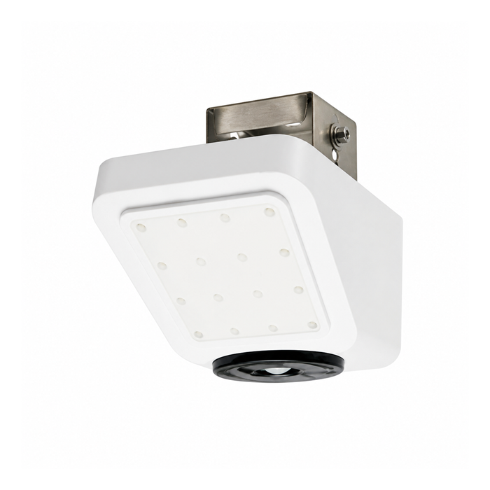
MV-RD2480 sensor and interface data
| Item | Product reference | Site check |
|---|---|---|
| Surface velocity | 0.10-25 m/s | Usable performance depends on flow conditions and the radar target; this is not a whole-channel mean-velocity range. |
| Level distance | 0.1-35 m | Measure from the antenna to the surface and allow clearance at maximum water level. |
| Radar frequencies | 24 GHz velocity / 120 GHz level | The two measurements serve different functions and require appropriate alignment. |
| Power supply | 9-28 V DC | Check voltage at the instrument under operating load and allow for cable loss. |
| Communication | RS485; Modbus RTU | Obtain the register map and scaling for the supplied firmware. |
| Housing | Aluminium alloy; IP67 | Install above the expected flood level; protect cable entries and external connections. |
| Operating temperature | -30 to 70 deg C | Check the environment at the mounted instrument and the ratings of associated equipment. |
Select a measuring section that can be checked
Look for a stable section with a representative surface-velocity target. Bends, local jets, backwater, vegetation and moving debris can make a convenient mounting point a poor measuring point. Survey the channel profile and document the alignment relative to the direction of flow. The final velocity angle and compensation settings must follow the supplied instrument's installation procedure.
Sediment accumulation or erosion changes the area corresponding to a given water level. Inspect the section after major flow events and reassess the stage-area relationship when the geometry changes. A fixed coefficient carried forward after a channel alteration can produce plausible-looking discharge values that no longer represent the site.
Connect to an RTU or data logger
The data path can run from MV-RD2480 through RS485 and Modbus RTU to an RTU or data logger, then onward to a telemetry platform. Check device address, serial settings, register type, units and invalid-value behaviour with the actual firmware. An interface description from a different flow-meter model is not a substitute for this information.
Log level and velocity with compatible timestamps and keep measurement-status information. A lost echo, out-of-range value or missing communication should not silently become zero discharge. Confirm how any calculated flow and accumulated volume respond to invalid inputs and power interruptions.
Open-channel measurement questions
Q1. Can the radar be installed without a weir or flume?
Yes, a non-contact velocity-area installation need not rely on a weir or flume, but it still needs a suitable measuring section and a validated discharge calculation. Surveying and reference measurements remain part of the project scope.
Q2. Does sensor accuracy establish the accuracy of reported flow?
No. Errors in the channel profile, datum, alignment and surface-to-mean velocity relationship also affect discharge. Agree a site acceptance method and operating range instead of treating an individual sensor specification as a guarantee for the completed station.
Q3. Will it measure flow inside a full pipe?
This arrangement requires an accessible free surface and a suitable radar path. A full pressurized pipe is a different measurement problem and needs an appropriate pipe-flow technology, not an open-channel installation assumption.
Q4. What should be supplied for an application review?
Send the channel cross-section, water-level and velocity ranges, mounting height, photographs in both flow directions, power supply and telemetry requirements. Describe sediment, backwater and debris conditions, and identify the available reference method for verifying discharge. For a project that needs only water level, the MV-RD12T water-level sensor may be the more relevant product to assess.
