


 Chinese
 Spanish
 Russian
 Portuguese
 French
 German
 Indonesian
 Thai
 Vietnamese
 Arabic
 Italian
 Turkish
 Polish
 Japanese



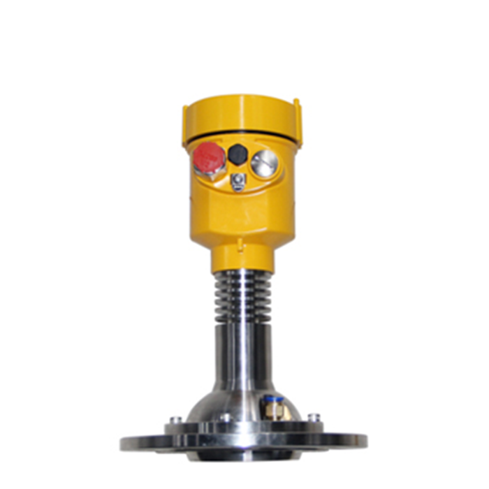
The METRAVON MV-RD21 measures powder and granule levels in silos using 80 GHz radar. Its 76 mm PTFE lens has a nominal 3-degree beam angle, with measuring-range configurations of 0.1-30 m and 0.3-150 m. The installation must account for the moving material surface: a reading taken at a filling peak can differ substantially from one taken near the wall.
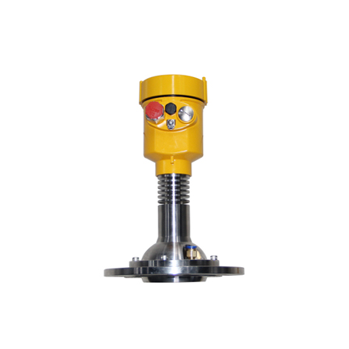
The level value represents one point on an uneven surface
Bulk solids do not form a flat surface. Filling creates a peak and discharge can create a valley, while material may build up on the wall. A radar reports the distance to the reflecting surface within its beam; it does not directly measure total inventory mass. The installation point should therefore be chosen according to the process question: high-level protection, operational level control or inventory trend.
For volume or mass estimates, define the vessel geometry and conversion method. A single-point reading cannot correct for angle of repose, asymmetric filling or changing bulk density. If purchasing and production need mass rather than level, compare the installation work and measurement limits described in silo weighing versus level measurement. High-level indication also needs a separate review of alarm location and failure response; no safety integrity rating is established by this product description.
MV-RD21 reference specification
Process-temperature construction and optional outputs vary. The selected range, antenna, flange, housing and output must be confirmed as one orderable configuration. Hazardous-area approval must be supported by the certificate for the ordered version rather than inferred from the product family.
Choose the measuring point before choosing accessories
Plot the fill inlet, extraction point, roof beams, ladders and internal bracing on the silo drawing. The radar should not look directly into the incoming stream. For a center-filled silo, an off-center mounting position may provide a more representative surface, but it still needs a rigid support and a clear beam path. Aiming hardware may be required when the roof angle or material profile prevents the antenna from looking at the intended target.
For a tall silo, include the full empty distance and the closest expected material distance. For a small bin, confirm that the near zone and nozzle do not consume the usable span. Dust does not automatically prevent radar measurement, but heavy airborne dust, low-reflectivity material and buildup on the lens can reduce echo margin. These are commissioning conditions, not details to leave until installation.
A narrow beam still widens with distance. The geometric diameter is approximately 2 x distance x tan(beam angle / 2). For a 3-degree beam, this is about 1.6 m at 30 m and 7.9 m at 150 m. These calculated widths help locate walls and braces on the silo drawing; they are not a hard boundary outside which echoes disappear.
Commission with real filling and discharge conditions
Start with verified silo geometry: radar reference point, empty distance, high-level limit and outlet position. Review the echo at empty or low level, then again while filling and after the material surface has formed. False echoes from roof structures should be identified from the echo trace rather than hidden by an arbitrary distance offset.
Before changing a distance offset, check where the reference reading was taken. A tape measurement near the wall and a radar aimed toward a central material peak are measuring different surfaces. Record both positions and the material condition. Adjusting the offset to make them agree can introduce an error at the next fill level.
Acceptance records for a silo project
- Nameplate, antenna, flange, range, supply and output match the approved submittal.
- Empty distance and high-level setpoint are measured from the radar reference point.
- The echo trace is saved at a known level and under representative dust conditions.
- The local distance and level values are compared with the PLC or DCS scaling.
- Filling and discharge trends move in the correct direction without unexplained jumps.
- Any volume or mass conversion states its vessel-geometry and bulk-density assumptions.
Procurement questions
Q1. Does a steady reading after filling prove the mounting position is correct?
It proves only that the instrument has found a stable echo at that moment. Observe a complete filling and discharge cycle, including the period of maximum dust. A beam that misses the inlet at low level may intersect the falling material or a changing peak later in the cycle.
Q2. What causes sudden jumps during filling?
The fill stream, strong dust echoes, a changing material peak or an internal structure can become the dominant reflection. Review the echo curve, installation angle and process state before changing offsets or filters.
Q3. Can this model replace a liquid-tank radar without a mounting review?
The lens size, flange, measuring range and aiming requirements differ from compact liquid instruments. Check the existing nozzle bore, length and connection against the MV-RD21 drawing. For a liquid application, start with a liquid-level radar such as the MV-RD11 and assess the liquid and process conditions separately.
Specify the silo, material and operating cycle
Request an MV-RD21 configuration review with the silo height and diameter, a roof drawing showing the inlet and outlet, nozzle dimensions, material name, particle size, moisture and filling method. Add temperature, pressure, power supply and the PLC or DCS interface. State whether the required result is operating level, free space or an inventory estimate so the proposed acceptance test measures the right quantity.
