


 Chinese
 Spanish
 Russian
 Portuguese
 French
 German
 Indonesian
 Thai
 Vietnamese
 Arabic
 Italian
 Turkish
 Polish
 Japanese



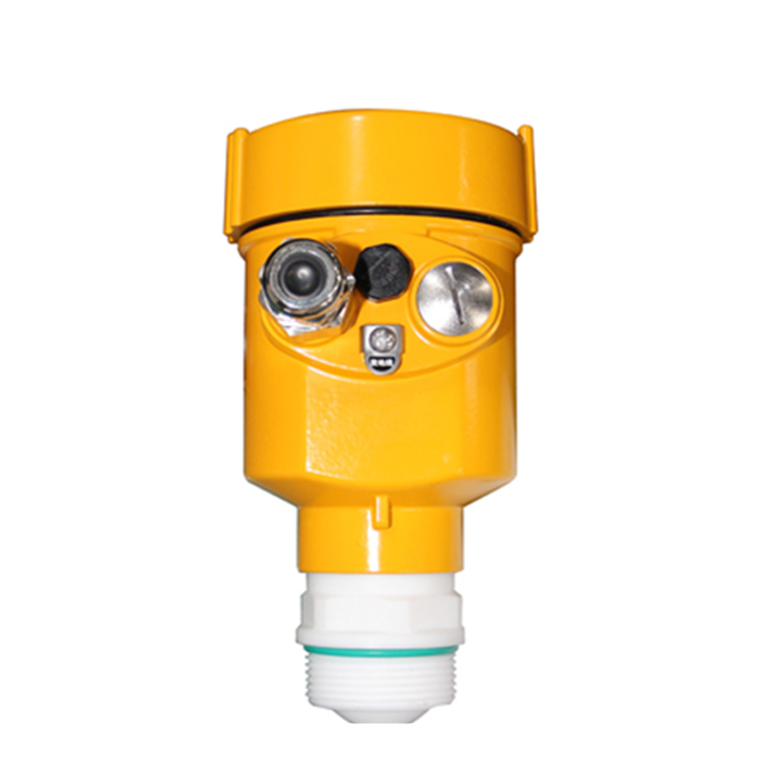
The METRAVON MV-RD11 is an 80 GHz radar level meter for liquid tanks and basins, with a maximum measuring distance of 30 m. Its 32 mm PTFE lens measures distance without contacting the liquid. Select the mounting position before ordering: a filling jet, thick foam or a long nozzle can prevent a usable surface echo even when the tank is within range.
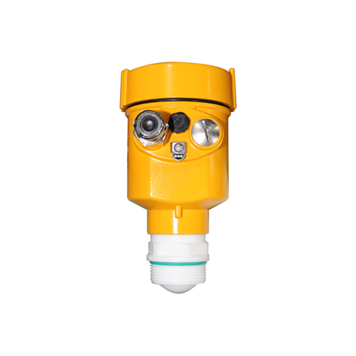
Where the MV-RD11 fits
Use the MV-RD11 as a candidate for atmospheric or low-pressure liquid duties such as water-treatment basins, utility-water tanks and process vessels with light agitation. A narrow radar beam helps when the available opening is small or internal structures limit the clear measuring path. It does not remove the need to check the nozzle, agitator, filling stream, foam, condensation and the highest permitted liquid level.
Do not approve the model from tank height alone. The working distance starts at the radar reference point, while the usable span must also leave room for the instrument's near-zone behavior and the project's high-level alarm. Heavy foam, persistent antenna buildup, a deep narrow nozzle or a mounting point directly above the filling stream can weaken the usable echo. Those conditions require a drawing or site photographs before a final configuration is selected.
MV-RD11 specifications for tank design
Reference values describe the product family, not every possible combination. Process connection, housing, seal, output and any hazardous-area requirement must appear on the approved datasheet or order code. Do not combine the maximum value from one construction with options that belong to another.
Mounting geometry determines the usable measurement
Choose a position that gives the antenna an unobstructed path to the liquid. Keep the beam away from the filling jet, ladders, heating coils and agitator blades. A long, narrow nozzle can act as an unwanted echo source, so its internal diameter and height should be included in the RFQ. If the vessel roof slopes, the mounting face should still keep the antenna directed toward the measured surface.
For an open basin, verify that the bracket cannot twist and that the measuring point is not directly above turbulent inflow or aeration. For a closed tank, verify that the process connection can be serviced without disturbing nearby pipework. Condensation management depends on the actual temperature cycle and installation; it should not be assumed from the enclosure rating.
Connect the radar to the control system
For a 4-20 mA loop, record the distance assigned to 4 mA and 20 mA, the engineering unit and whether the PLC value represents distance, level or percentage. Confirm available loop voltage after cable loss and input load. HART communication does not replace the analog scaling check.
When an RS485/Modbus configuration is requested, include the required register map, baud rate, parity, device address plan and whether the PLC, RTU or data logger will act as the master. RS485 is an interface and Modbus is a protocol; both must match the selected instrument configuration and the receiving system.
For a level calculation, use level = empty reference distance - measured distance. As a calculation example, an empty distance of 6 m and a measured distance of 2 m give a 4 m level. If the configured 4-20 mA span is 0-5 m of level, the expected current is 16.8 mA. These are example settings, not factory defaults. Checking this relationship exposes a PLC configured for distance when the transmitter is reporting level.
Commissioning and acceptance sequence
- Check the nameplate, process connection, antenna, power supply and output against the approved order.
- Measure the empty distance from the same reference point used in the instrument configuration.
- Enter the empty and full reference distances, then confirm the displayed engineering unit.
- Review the echo with the vessel empty or at a known level; record any false-echo suppression applied.
- Compare the local value with the PLC or DCS value at a known low, middle or high level when the process permits.
- Test high-level alarms below the near zone and record the final setpoints, damping and fault behavior.
A stable local display does not prove that the control-room value is correct. Acceptance must cover both the radar reading and the complete signal path, including scaling and alarm logic.
Questions that change the quotation
Q1. Why does the local display agree with a dip reading but the PLC does not?
First compare the variables: distance decreases as level rises. Check whether both devices use level, distance or percentage, then compare zero, span and units. Measure loop current against the configured endpoints before changing the radar calibration. A scaling error downstream should be corrected at the receiving channel.
Q2. Will the radar measure through thick foam?
Foam behavior depends on thickness, density and process conditions. Light or intermittent foam may be manageable, but persistent thick foam can reduce the reflected signal. Describe the foam and provide operating photographs rather than assuming a guaranteed result.
Q3. Is a PTFE antenna enough for a corrosive liquid?
Not by itself. The antenna, process connection, seal and any exposed metal must all be checked against the liquid concentration and temperature. Material compatibility should be documented for the ordered construction.
Q4. What is required for a replacement installation?
Send the existing opening size, nozzle height, old instrument supply and output, wiring, control-system scaling and a photograph showing internal obstacles. A matching thread or flange does not prove signal or process compatibility.
Send the tank drawing with your inquiry
For an MV-RD11 quotation, include the liquid, empty and full distances, temperature and pressure, nozzle bore and height, connection size, foam conditions and required output. A marked tank drawing lets the mounting location and antenna clearance be reviewed together. Specify any hazardous-area classification and chemical compatibility requirements. For other antenna sizes or process conditions, review the radar level meter range.
