


 Chinese
 Spanish
 Russian
 Portuguese
 French
 German
 Indonesian
 Thai
 Vietnamese
 Arabic
 Italian
 Turkish
 Polish
 Japanese


2-Wire, 3-Wire and 4-Wire Transmitters: Powering the Loop Correctly
"How many wires does this transmitter need?" is a wiring question, but it is really a power question. A transmitter has to do two jobs — measure and communicate — and the number of wires is decided by where its power comes from. Get this wrong and the loop will not power, will read wrong, or will burn a card.
The loop-powered 2-wire transmitter
A 2-wire transmitter runs entirely on the current in the loop itself. The same two wires carry both the DC power and the 4–20 mA signal. There is no separate supply cable: the transmitter is a "loop-powered" device, and the 24 V DC supply is placed in series with the loop at the panel or marshalling end.
This is the standard for the overwhelming majority of process transmitters — pressure, temperature, level, flow — because it needs only two wires per device and is intrinsically simple. The trade-off is a strict power budget: the transmitter's entire electronics must run on the minimum current available in its specified operating and fault modes while keeping the signal current correct. That is why 2-wire devices have limited internal power for things like large displays or heated sensors.
| Property | 2-wire | 3-wire | 4-wire |
|---|---|---|---|
| Power source | Same pair as the signal in a loop-powered design | Separate supply with a shared reference | Separate power pair and signal pair |
| Typical output | 4–20 mA | Current or voltage, design-specific | Current or voltage, design-specific |
| Power budget | Limited by loop voltage and minimum current | Supply and common-conductor limits | Separate supply rating |
| Isolation | Check the actual specification | Check the actual specification | Not guaranteed by four wires |
| Connection check | Loop supply and compatible input | Output type, common and source/sink behaviour | Power rating and active/passive output |
The 3-wire compromise
A 3-wire transmitter has two power wires plus a third wire for the signal, sharing one common conductor. It exists for devices that need more power than a loop can supply but where the manufacturer wants to save a wire against a full 4-wire connection. The 3-wire scheme usually carries a voltage output (0–10 V) or a 4–20 mA output referenced to the same common as the supply.
The shared common in a three-wire device deserves attention. Common-wire voltage drop directly affects a referenced voltage signal; a current output behaves differently until its compliance or common-mode limit is exceeded. Check conductor resistance, input type and allowable reference differences for the actual circuit.
The self-powered 4-wire transmitter
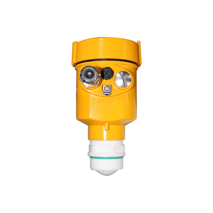
A 4-wire transmitter has two wires for its own power supply (usually 24 V DC or 110/220 V AC) and two separate wires for the output signal, which may or may not be galvanically isolated from each other. It is used where the device needs real power: radar transmitters with antenna heating, analytical instruments, flow computers, and any transmitter with a large local display or a relay output.
A four-wire design provides a separate power budget. Isolation is an additional specification to verify between supply, signal, sensor and earth; it does not follow from conductor count. Also check whether its current output is active or passive before connecting it to a powered input.
The voltage-drop calculation that decides a loop
For a loop-powered current circuit, the supply must cover the transmitter’s minimum terminal voltage, round-trip cable resistance, series loads and associated-equipment drops. A separate-power voltage output uses a different loading calculation. For the current loop:
Supply voltage ≥ minimum transmitter voltage + Imax × total series resistance + other specified voltage drops, with design margin.
At 20 mA, assumed values of 12 V minimum transmitter voltage, a 250 ohm load and a 150 ohm round-trip cable consume 12 + 5 + 3 = 20 V, leaving 4 V from a 24 V source. At 22 mA the same resistive loads consume 8.8 V, leaving 3.2 V. Check actual maximum current, minimum supply, barriers and tolerance before accepting the margin.
Choosing the right scheme
Standard 4–20 mA measurement → consider a two-wire instrument when its power and response requirements fit the application.
A powered sensor or a device with a modest power need → 3-wire, but watch the shared common for ground errors.
A device with a larger power demand → use its specified separate-power arrangement; verify isolation and output type explicitly.
A safety or critical loop → follow the safety manual and approved architecture, including supply reliability, diagnostics and the worst-case voltage budget. Wire count alone does not establish suitability.
Questions technicians ask
Q1. Can I loop-power a 4-wire transmitter?
Not unless its manufacturer explicitly provides a loop-powered operating configuration. A separate-power device needs its rated supply; the current-output pair alone does not supply its electronics.
Q2. Why is 24 V DC common rather than 12 V?
It often provides useful headroom for transmitter voltage, cable resistance and series loads. Select the supply within every device and circuit rating. No single DC voltage threshold guarantees touch safety under all wet, hazardous-area or fault conditions.
Q3. What happens if I wire a 2-wire transmitter to a 3-wire card?
Check the actual terminals and whether the input supplies loop power or only measures current. Some inputs support several arrangements. Use the approved circuit diagram; conductor-count labels alone do not determine compatibility.
Q4. Does a 4-wire transmitter need a separate isolator?
Check its isolation specification, output type and the input common-mode limits. Some already provide the required isolation; others do not. Four wires are not evidence of galvanic separation.
