


 Chinese
 Spanish
 Russian
 Portuguese
 French
 German
 Indonesian
 Thai
 Vietnamese
 Arabic
 Italian
 Turkish
 Polish
 Japanese


Radar Level Transmitter Retrofit on an Existing Tank: What Can Be Reused
A radar retrofit should begin with a survey of the connection, measuring path, electrical loop and required function. Reusing a nozzle or cable can reduce work, but only after its suitability is established. There is no universal bore or nozzle-length threshold that makes every installation a drop-in replacement.
What problem should the retrofit solve?
Record why the existing measurement is being replaced: unreliable target tracking, density-related error, maintenance access, damaged hardware, obsolete spares or a changed process. Confirm that the replacement measures the same variable required by the control or inventory system.
| Existing arrangement | What to investigate before choosing radar |
|---|---|
| DP or hydrostatic | Pressure taps, density assumptions, pressure reference and available top access |
| Float or servo | Required gauging role, mounting reference and any existing pipe geometry |
| Ultrasonic | Bracket position, acoustic-path problems and suitability of a radar measuring path |
| Capacitance probe | Connection, contact-material history and the purpose of the old measurement |
| Manual gauge or sight glass | Safe reference method and the infrastructure needed for continuous measurement |
An intact remote-seal capillary contains its specified fill fluid; process blockage of an impulse line and coating of a diaphragm are different problems. Do not justify a retrofit using the incorrect claim that process product normally blocks the sealed capillary.
Which parts can be reused?
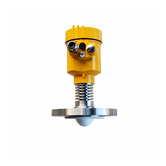
Inspect the actual nozzle bore, length, angle, flange or thread, internal steps and condition. Check whether the proposed antenna is permitted inside, below or above the connection. An adapter may solve a mechanical fit without solving an echo, pressure or cleaning problem.
The existing cable may be usable if its type, condition, route, shielding and electrical characteristics meet the new design. Recalculate terminal voltage and the required protection assessment. Confirm that the receiving card accepts the new output and its fault states.
Do not assume a DP tapping or sight-glass connection becomes a suitable radar access point. Equally, do not declare every small connection unusable without reviewing the actual antenna or probe options. The assembly's installation instructions and vessel design determine what is feasible.
How should the nozzle and beam be checked?
| Survey item | Evidence needed |
|---|---|
| Reference plane | A drawing that relates the sensor reference to the plant level datum |
| Nozzle geometry | Measured clear bore, length, angle, internal steps and antenna position |
| Beam clearance | Full-range check against wall, inlet, fittings and moving internals |
| High-level end | Minimum distance and near-end restrictions at the maximum required level |
| Low-level end | Maximum distance, bottom reflections and any probe end limitations |
| Process boundary | Suitable connection, materials, ratings and mechanical support |
A long nozzle can create structural echoes or a restricted near-end region. That is not automatically a loss of the bottom of the tank range. Distinguish high-level limitations near the antenna from separate bottom or weak-echo issues.
Do not map every internal object simply because it appears in the curve. Suppression settings must follow the model's procedure and avoid the real changing surface. Never copy a false-echo map from another tank.
Can the work be done while the tank remains in service?
Only the site's approved isolation and work process can answer that. A single closed valve is not universal proof of safe isolation. Trapped pressure, vapour, liquid, temperature and valve integrity must be considered before a process connection is disturbed.
Determine the required outage, isolation, pressure release, decontamination and permits with the responsible operations and engineering team. Do not open a live tank connection or perform vessel modification on the strength of a generic retrofit guide.
Plan temporary measurement and protection where the instrument will be unavailable. A continuous level replacement must not silently disable a required alarm or independent protective function. The change should include the appropriate management-of-change review.
What commissioning sequence should be agreed?
- Confirm the installed assembly, process ratings, protection requirements and mechanical completion against the approved design.
- Establish the sensor reference and plant datum, then enter the required geometry and operating range.
- Check supply, wiring, output scaling, units, communication and the defined fault and stale-data response.
- Record echo and diagnostic information at known operating states, retaining the original settings before any suppression changes.
- Compare readings with a safe appropriate reference over representative levels and process conditions where practical.
- Test the agreed alarm and protective paths using approved methods, restore normal operation and record the as-left configuration.
A signal-injection test does not establish correct radar target tracking. A stable echo does not independently establish absolute accuracy. Select tests that collectively cover the measurement, output chain and required function.
Which late problems should the handover prevent?
A transmitter and PLC may use different ranges while both displays look plausible. An old hydrostatic datum may differ from the radar reference. A new output version may not communicate through the old barrier or host. Check these interfaces explicitly rather than treating successful power-up as completion.
The process can also change after startup. Keep evidence from filling, agitation, condensation or dusty operation as relevant, not just a calm commissioning snapshot. Define who will review early operating trends and what triggers a follow-up inspection.
How should the retrofit quotation be scoped?
Separate the instrument from adapters, connection work, access, isolation, wiring, configuration and acceptance. Do not promise a half-shift swap or a fixed cost multiplier before the survey. Special materials, vessel work and approvals can set the schedule.
Provide METRAVON with the existing tag, full model details, loop drawing, connection photographs, tank drawing and failure history. Request a proposal that identifies what can be reused, what must change and how the completed installation will be verified.
FAQ
Can a DP transmitter be replaced without welding?
Sometimes, if an existing approved connection and measuring path suit the proposed instrument. A DP impulse tapping is not automatically suitable, and any vessel modification needs the responsible engineering review.
Is 50 mm the minimum nozzle diameter for every radar?
No. Connections and antenna or probe arrangements vary by model. Check the actual clear bore, length and approved installation drawing.
Is closing the isolation valve enough to remove a transmitter?
Not universally. Follow the site's approved isolation, pressure-release, decontamination and permit procedures. Consider trapped contents and the required isolation standard.
Can the old current-loop cable be reused?
Only after its condition and electrical characteristics are checked against the new instrument, supply, receiver and applicable protection design.
Must the tank be manually gauged after the retrofit?
Use a safe suitable reference method and agreed acceptance plan. Manual gauging is one possible method, not a reason to open a hazardous tank.
What must be handed over after commissioning?
Retain reference geometry, model and certificate information, wiring, settings, comparison results, echo records and completed alarm or fault tests, with clear responsibility for follow-up.
Related applications
Radar Level Antenna Types: Horn, Lens, Encapsulated and Guided Wave | Radar Level Transmitter Accuracy: What the Datasheet Number Does Not Tell You
