


 Chinese
 Spanish
 Russian
 Portuguese
 French
 German
 Indonesian
 Thai
 Vietnamese
 Arabic
 Italian
 Turkish
 Polish
 Japanese


Radar Level Measurement in Narrow Silos: Beam Clearance
Draw the antenna pattern against the silo section at the lowest operating level. Wall clearance, filling geometry and deposits determine how difficult surface tracking will be. Beam overlap is a risk to evaluate with the actual instrument, not an automatic proof that measurement is impossible.
The beam-versus-wall calculation
Use the manufacturer’s stated beam-angle convention. Many datasheets give a full beam angle alpha; the nominal radius at distance H is then H × tan(alpha/2). If theta is explicitly the half-angle, the equivalent expression is:
r = H × tan θ
Compare the nominal footprint with the available wall clearance and relevant internals. A published beam angle is not a hard boundary beyond which no energy exists. Adequate nominal clearance helps, but echo verification is still necessary.
Worked comparison. Silo Ø 3 m (wall radius 1.5 m), sensor on the centreline, lowest level of interest 15 m below the antenna:
Assumed instrument A: a 6° full angle (3° half-angle) gives r = 15 × tan(3°), approximately 0.79 m. It fits inside a 1.5 m wall radius in this centred example. These are assumed angles, not specifications guaranteed by 80 GHz.
Assumed instrument B: a 20° full angle (10° half-angle) gives r = 15 × tan(10°), approximately 2.65 m. Its nominal cone reaches a 1.5 m radius at about 8.5 m, increasing wall-interference risk. This is not a universal 26 GHz beam angle or a guarantee of measurement failure.
The example compares two antenna patterns, not frequency labels alone. A larger aperture may narrow the beam at a given frequency. For each candidate compare the actual antenna, nozzle fit, dust performance and full operating distance.
Mounting position when centreline is not available
Some silos cannot take a centreline nozzle — roof structure, existing manways, retrofit constraints. Off-centre mounting changes the geometry: measure the horizontal distance from the nozzle axis to the nearest wall in the beam's direction, not just the silo radius, and use that clearance in the r calculation. Also check the opposite direction: an off-centre beam may now cross the fill stream, which was avoidable from the centre.
A liquid-service stilling pipe is generally not a remedy for grain, pellets or cohesive powder: bridging or stagnant material can prevent representative filling and emptying. If no free-space position works, review an approved solids probe, additional measuring locations or weighing, including roof loads and mechanical forces.
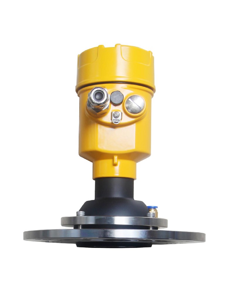
Wall echoes are the narrow silo's chronic disease
Even when the beam fits geometrically, a narrow metal wall close to the beam returns a strong ringing echo that the device can mistake for surface or use as a false reference. Modern transmitters handle this with echo mapping: during commissioning, the device records identified fixed wall and fitting echoes within a controlled range, and the algorithm tracks the true surface among the rest.
Mapping done right:
Carry out false-echo suppression at a known material level according to the manufacturer’s instructions. Limit the taught range so it does not suppress the true surface or needed low-level echoes.
After the first fills, compare echo curves and tracking with the commissioning baseline. Do not automatically teach new deposits or the material surface as fixed obstructions; identify the cause before changing suppression.
Schedule a re-map after any lining repair, weld work, or new internal fitting.
Keep the echo curves from commissioning; they are the baseline for every later "the reading is wrong" conversation.
In plastic or concrete silos the wall echo is weaker but the transmission losses are different; do not transfer a steel-silo configuration file to a non-metal silo without review.
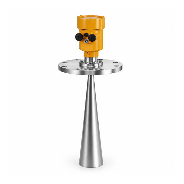
Accuracy expectations in narrow silos
The surface in a narrow silo is rarely flat at the beam location: filling peaks the product under the inlet, discharge funnels it over the outlet, and wall adhesion leaves a ragged ring. A beam that measures a 0.3 m patch reports that patch. State the accuracy requirement against a defined reference state — settled, level surface at a known inventory — and treat live readings as inventory indication with a stated band, not as measurement to the millimetre.
Questions from narrow silo projects
Q1. Is a bigger antenna always better in a narrow silo?
Bigger antennas give narrower beams but need bigger nozzles and cleaner mounting geometry. In a Ø 3 m silo a compact 80 GHz unit often fits the nozzle reality better than a large horn.
Q2. What if the beam hits the fill stream?
Prefer relocating or aiming the sensor, or an engineered change to the inlet that preserves flow and mechanical safety. A moving stream cannot generally be removed with a permanent false-echo map. Verify tracking through the fill cycle.
Q3. Does a rope-guided probe solve everything?
A guided wave probe with a flexible cable avoids the beam-spread question entirely and tolerates narrow geometry well, but cable wear in abrasive solids and any required support or anchoring must be assessed; a bottom anchor is not mandatory for every cable design. It is a legitimate answer, not a free one.
