


 Chinese
 Spanish
 Russian
 Portuguese
 French
 German
 Indonesian
 Thai
 Vietnamese
 Arabic
 Italian
 Turkish
 Polish
 Japanese


Molten Salt Level Measurement in Tanks: Heat Path Design
Salt deposits or a frozen obstruction can block a radar path and leave a plausible but stale reading. Common nitrate solar-salt systems operate across a wide temperature range; obtain the actual blend’s freezing, melting and operating limits. The nozzle thermal design must preserve a clear path without exceeding antenna, seal or electronics ratings.
Design the heat path, not just the temperature rating
Define which parts can contact salt or collect deposits, and their required thermal envelope. Some parts may need heating while the instrument neck or electronics needs cooling or a thermal break. Do not assume the entire assembly should be held at one temperature. Review the heat path with the instrument and process designers.
| Design provision | Purpose | Check |
|---|---|---|
| Approved thermal extension | Limit heat transfer to the instrument | Maximum and minimum temperatures at each interface |
| Nozzle heat tracing | Prevent freezing where salt can collect | Calculated heat loss, startup duty and measured control temperature |
| Insulation | Reduce unwanted heat loss | Keep required cooling surfaces and electronics outside the heated insulation |
| Compatible purge where approved | Reduce deposition or protect a specified interface | Gas temperature, flow, cooling effect and supply-failure response |
| Remote electronics where available | Separate electronics from process heat | Approved sensor head, interconnection and temperature ratings |
Worked heat path. Take an illustrative bare pipe 0.15 m in diameter and 0.5 m long, with a uniform outer surface at 300 °C in −10 °C air. With assumed convection coefficient 10 W/(m²·K) and emissivity 0.8, its lateral area is about 0.236 m². Convection is about 730 W and net radiation about 1,100 W: roughly 1.83 kW before flange losses. This simplified bare-pipe example shows why a universal 300 W trace recommendation is unsound. Size the actual insulated assembly from its temperature distribution, insulation, wind, flange and startup requirements; do not apply this bare-pipe result directly as a heater rating.
Why non-contact radar is the usual choice
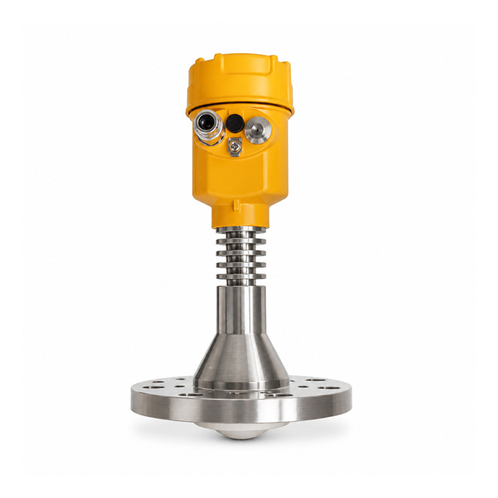
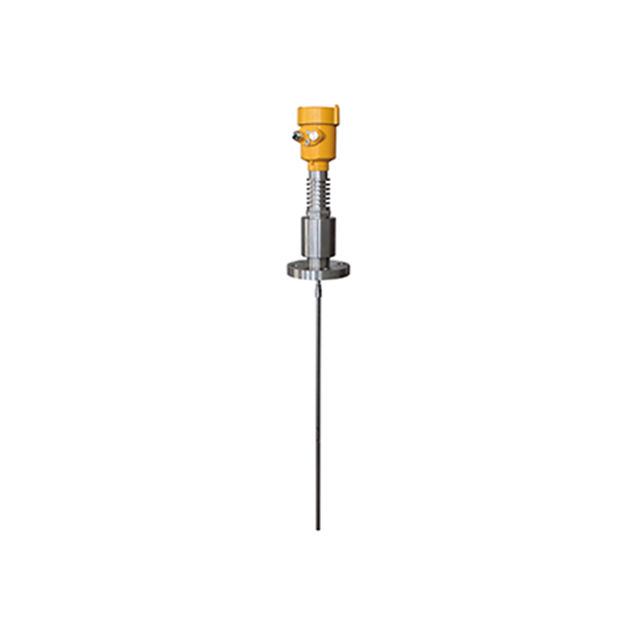
A suitable high-temperature non-contact radar avoids a probe immersed in molten salt, but its complete process interface must be qualified for the salt, temperature and thermal cycling. Guided-wave probes, pressure taps and weighing have different mechanical and thermal requirements. Confirm the selected instrument’s real limits; a thermal extension or purge does not upgrade its pressure, temperature or chemical rating.
Startup and shutdown are the dangerous hours
At steady state the system is warm and stable. The risky periods are startup (cold salt, heating circuits not yet balanced) and shutdown (salt draining, trace still needed for days). Two procedures belong in the operations manual:
Trace energized before salt reaches the nozzle during startup, verified by a surface temperature check at the flange — not by the trace's indicator light.
Maintain the approved heat-tracing and drain-down sequence until salt has been removed or held safely above its relevant freezing limits. Verify temperatures at designated cold points; shutdown is not complete merely because a fixed hold time has elapsed.
Use stale-value and rate-of-change checks against independent transfer or operating evidence to flag a possible blocked path. A frozen nozzle is one possible cause, alongside signal loss or communication failure. Hold the value as suspect and follow the approved response; a flat trend alone is not a diagnosis.
Materials and verification
Wetted nozzle and flange materials must cover the salt temperature with margin and the thermal cycling regime; 300-series stainless is common in salt service, but the project's material selection governs.
Select gaskets for the exact salt chemistry, maximum temperature, oxidising conditions, joint design and thermal cycling. Do not assume graphite, a polymer or any generic high-temperature gasket is compatible with hot nitrate salt; obtain explicit material approval.
Any instrument verification happens against known inventory events — a certified transfer in or out — because physical access to a 500 °C salt surface for a manual check is not a maintenance task.
Questions from thermal storage projects
Q1. Can thermal oil use the same design?
Use its own pour point, viscosity and thermal-stability limits. Some oils require cold-start heating or freeze protection. Also assess vapour condensation, oxygen exposure and fire risk; a molten-salt nozzle design cannot simply be transferred to an oil tank.
Q2. What accuracy is realistic?
The salt surface is calm and reflective at steady state; accuracy follows the device and the geometry. During bubbling or agitation for temperature homogenization, the surface moves and averaging applies as in any agitated tank.
Q3. Is fibre-optic or laser an alternative?
Assess the actual measurement principle, optical access, temperature rating and fouling provisions. An optical window and a radar process window can both suffer deposits. Remote electronics alone does not establish that either system will work in the nozzle.
Related technical guides
- How to Specify a Radar Level Transmitter: The 14 Fields That Decide the Quote
- Radar Level Antenna Types: Horn, Lens, Encapsulated and Guided Wave
Discuss your measurement application with METRAVON
