


 Chinese
 Spanish
 Russian
 Portuguese
 French
 German
 Indonesian
 Thai
 Vietnamese
 Arabic
 Italian
 Turkish
 Polish
 Japanese


Radar level antenna selection starts at the vessel opening. The antenna has to fit the nozzle, send its beam past internal structures and remain usable when vapour condenses or material collects on its surface. A sensor with enough measuring range can still give unreliable readings if the mounting arrangement obstructs its signal. METRAVON rod, horn, parabolic and lens configurations address different combinations of these constraints.
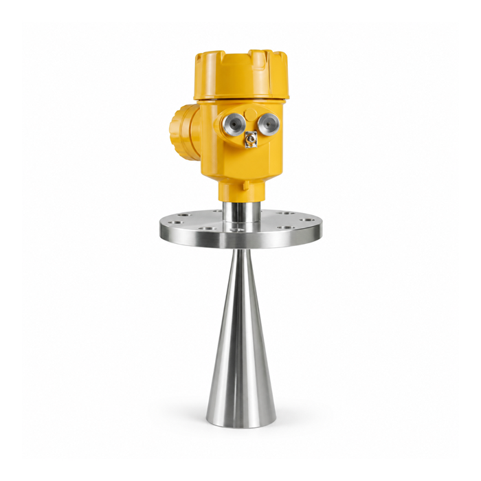
Radar level antenna selection: compare the physical assemblies
An antenna name is not a pressure rating or a chemical-compatibility statement. The following models illustrate actual METRAVON constructions. They are starting points for a drawing review, not interchangeable fittings.
| Construction | Model and installation consequence |
|---|---|
| PTFE rod | MV-RD901 uses a projecting PTFE rod antenna for atmospheric liquid tanks. Check its length against the nozzle; it is not an immersed guided wave probe. |
| Metal horn | MV-RD902 offers different horn diameters. Clearance for the mouth, neck and flange matters as much as the nominal connection size. |
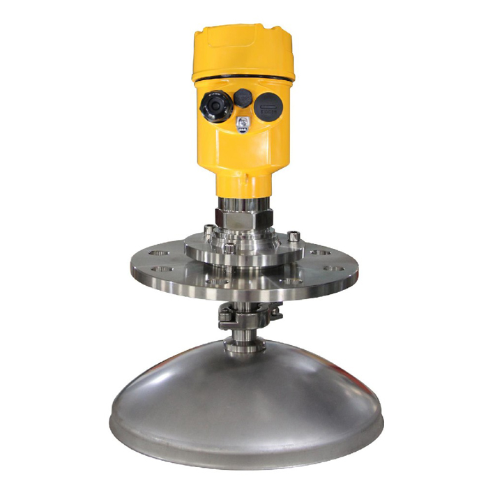
| Parabolic reflector | MV-RD904 lists 196 mm and 242 mm reflectors. Confirm how the assembly can pass through the opening and be removed for maintenance. |
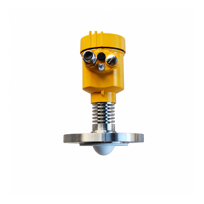
| Lens | MV-RD14G has a 44 mm PTFE lens. A compact antenna does not remove the need to check the nozzle bore and the surrounding beam path. |
Read the nozzle section, not just the flange designation
Ask for a section drawing showing the internal diameter, nozzle height, flange face, internal welds and any reducer. A DN designation alone cannot show whether a horn is recessed behind a shoulder or whether a lens looks down a long, narrow tube. These details can introduce reflections close to the antenna, where they may compete with the high-level measurement.
Do not adopt a universal rule that every antenna must project by the same distance. Some assemblies are designed for flush mounting; others require projection below the nozzle. Use the installation dimensions for the selected antenna. If the existing nozzle is unsuitable, compare a different antenna or an approved mounting change before relying on false-echo suppression.
A larger reflector can also create a practical maintenance problem. Check the access hatch, lifting route and room to release the flange bolts. An instrument that fits during vessel construction may be difficult to replace once nearby pipes and cable trays have been installed.
Check beam clearance at the lowest operating level
The beam occupies more space as the distance increases. A clear path near the top of a tank does not prove clearance when the tank is nearly empty. Mark ladders, coils, support members and filling pipes on the vessel section, then examine the whole operating range rather than one liquid level.
For an initial geometric check, nominal beam diameter is approximately 2 x distance x tan(full beam angle / 2). At a distance of 20 m, a 6-degree beam gives about 2.10 m and a 3-degree beam about 1.05 m. These are calculated cone widths, not measured performance or mandatory wall-clearance values. Antenna patterns do not end abruptly at the quoted angle; strong objects outside that cone may still produce echoes.
For bulk solids, position the measurement point with the filling and discharge pattern in mind. A narrow beam aimed at a changing pile apex may track that local height accurately without representing average stock. Beam clearance and a useful measurement location are separate requirements.
Review deposits and exposed materials
Chemical vapour can contact seals, connection materials and metal parts even when the antenna itself is PTFE. Supply the chemical concentration and operating temperature, including cleaning conditions. Selecting the antenna polymer alone is not a complete corrosion review.
Dust suspended in the vessel and a layer attached to the antenna are different problems. Inspect whether deposits can form on the emitting surface, inside a horn or around a reflector. A smooth lens may simplify cleaning, but it is not proof that cleaning will never be needed. Where a purge arrangement is proposed, confirm that the specific assembly has a suitable connection and obtain its utility requirements before ordering.
Questions about installation and replacement
Q1. Can a larger horn be fitted to an existing transmitter?
Not solely because the parts appear to fit. The antenna, process seal, electronics configuration and calibration belong to an approved instrument assembly. Send the complete order code and existing drawing before requesting an antenna change; otherwise the replacement may alter both the measurement reference and the pressure boundary.
Q2. Will a narrow beam solve interference from an agitator?
Only if the beam can avoid the moving blades and shaft throughout their travel. A stationary photograph can miss that interference. Review the blade envelope and compare readings with the agitator running and stopped. Damping can slow a fluctuating indication, but it cannot establish that the instrument is tracking the correct surface.
Q3. Is a stilling well a substitute for a guided wave probe?
No. Free-space radar in a pipe needs an instrument configuration suitable for that pipe geometry, with attention to joints, bore and liquid exchange. Guided wave radar uses its own rod, cable or coaxial probe. Do not transfer installation clearances or calibration assumptions between these arrangements.
Summary
Choose the antenna by its installed geometry and service conditions, then verify the complete instrument. For a mounting review and quotation, send a nozzle section, the minimum and maximum surface positions, internal-obstruction drawings, media details and photographs of the available access. These documents help identify a workable assembly before a flange or antenna is ordered.
