


 Chinese
 Spanish
 Russian
 Portuguese
 French
 German
 Indonesian
 Thai
 Vietnamese
 Arabic
 Italian
 Turkish
 Polish
 Japanese


Radar level meter selection should begin with the value the control system needs. A liquid height for pump control, the surface of a material pile and an interface between two liquids are different measurements. METRAVON free-space and guided wave instruments can be considered for these duties, but the required output must be defined before comparing range, frequency or antenna size.
Define what the level signal must represent
For a storage tank, identify the reference elevation, normal operating band and highest permitted surface position. If the PLC needs volume, it also needs an appropriate vessel conversion. If it needs mass, density or another independently supported measurement is required. A distance sensor does not directly weigh the contents.
In a silo, the measured surface may be a pile, a discharge funnel or material adhering to a wall. Decide whether the reading is for filling control, stock estimation or a low-level warning. One measurement location may not serve all three purposes equally well. Record which location the reading represents so that operators do not mistake a local height for average inventory.
For interface measurement, state whether total liquid level, the lower phase level or both must be available. Do not describe the duty simply as an oil tank: phase properties and an emulsion layer can determine whether the required interface can be detected.
Radar level meter selection by process duty
| Duty | METRAVON route to assess |
|---|---|
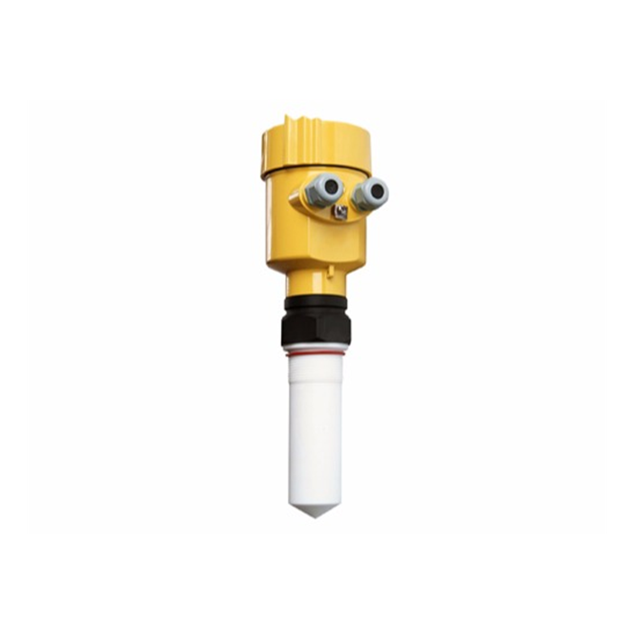
| Atmospheric liquid tank | MV-RD901 provides a PTFE rod-antenna option. Check chemical exposure and its listed distance range; do not transfer this atmospheric configuration to a pressurised reactor. |
| Heated liquid vessel | MV-RD15G is a liquid-duty 80 GHz option. The antenna, seal and connection must match the combined operating temperature and pressure. |
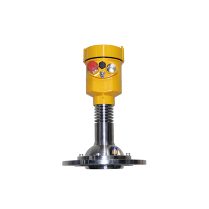
| Hot bulk solids | MV-RD21G is a solids-duty configuration. Review pile position, filling stream and its own pressure limit, not the limit of a similar-looking liquid model. |
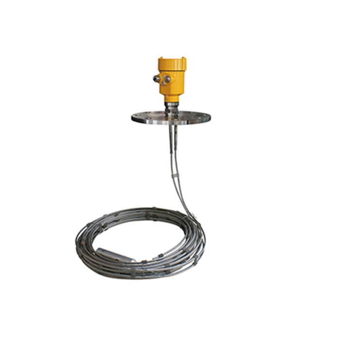
| Liquid interface | MV-RD703 has a liquid-duty dual-cable configuration for evaluation. Interface capability depends on the order configuration, phases and emulsion conditions. |
The model comparison narrows the investigation; it does not approve the application. Reject a candidate if its probe cannot be kept clear of moving equipment, its materials are incompatible or the required high level falls inside an unusable near zone. Those issues cannot be resolved merely by selecting a longer measuring range.
Separate mechanical approval from the instrument specification
List normal and maximum process conditions together with cleaning, startup and shutdown conditions. The pressure-temperature envelope of the assembled instrument matters: the highest temperature and highest pressure printed separately in a catalogue are not automatically permitted at the same time. Also check the temperature around the housing, particularly when the nozzle sits inside insulation.
For free-space radar, examine the nozzle and the path to the lowest operating surface. For guided wave radar, examine the full probe length, its movement and removal space. The former needs a usable beam path; the latter introduces a physical component into the process. Sticky product, strong flow and maintenance access can change which approach is practical.
Specify the entire signal path
A typical analog arrangement is transmitter to 4-20 mA input to PLC or RTU. The order must state whether the input supplies loop power, the available voltage and any isolator or barrier. HART communication requires compatible loop equipment; a normal analog input can read current without providing HART diagnostics.
Where RS485 with Modbus RTU is required, request the corresponding electronics and register documentation. Agree on the variable, units, data representation and invalid-reading status. A data logger that stores a numeric value but ignores instrument faults can preserve misleading records after an echo is lost. Neither RS485 wiring nor a gateway automatically establishes the complete application protocol.
Set the analog endpoints explicitly. Both transmitter and receiver must agree on whether 4 mA represents zero level, an elevated minimum level or another configured value. A correct local reading with an incorrect PLC display is often a scaling or configuration issue, not evidence that the antenna is unsuitable.
Make the quotation and acceptance requirements match
Send the same drawing and operating-condition sheet to everyone quoting the instrument. Request the selected antenna or probe, connection standard, materials, electrical option and any required approvals as identifiable items. Separate the cost of mounting changes, barriers, communications equipment and commissioning from the transmitter price. Without that separation, a low unit price can exclude equipment the installation needs.
Before accepting the system, compare the local value, transmitted signal and PLC value at known process conditions. Include filling or agitation if those are normal operations. Record the reference method, expected uncertainty and allowed error before testing; a single catalogue accuracy figure is not a site acceptance procedure. Check the configured response to a lost signal without creating an unsafe process condition.
Questions that change the selection
Q1. Does a maximum range longer than the tank height prove suitability?
No. The lowest surface must return a usable echo under the actual process conditions, while the highest surface must remain outside the selected instrument's near zone. Check both endpoints from the specified measurement reference. Nozzle height, a sloping roof or an elevated mounting bracket can change those distances.
Q2. Can one radar provide the measurement and all overfill protection?
Do not assume that a continuous reading makes a complete protection system. Determine the required alarm and shutdown architecture through the project's risk assessment. A sensor, logic function and final element need suitable design and testing; neither a model name nor a display alarm establishes an independently approved safety function.
Q3. What should be investigated before replacing an unstable instrument?
Record when the problem occurs and compare the local reading, echo indication and receiver value. Inspect deposits, the filling path, supply and wiring before changing hardware. A problem that appears only during filling calls for a different investigation from a steady local value with a fluctuating control-system display.
Summary
A useful enquiry defines the measured variable, operating conditions, installed geometry and receiver requirements, then states how the result will be checked. Send those details with the existing instrument code, where applicable, to METRAVON for model and quotation review. Resolve unsuitable process connections or inaccessible mounting positions before committing to a transmitter.
