Chinese
 Spanish
 Russian
 Portuguese
 French
 German
 Indonesian
 Thai
 Vietnamese
 Arabic
 Italian
 Turkish
 Polish
 Japanese

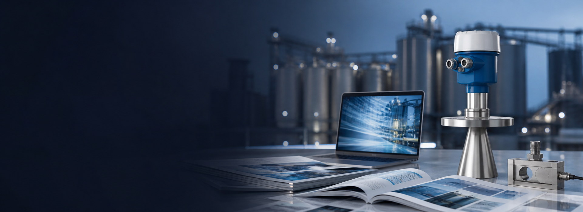
A radar level transmitter leaves the factory with a datasheet accuracy of a few millimetres, but the number that decides whether a tank inventory is accepted is the error accumulated after the instrument is mounted, wired and scaled. Radar level measurement accuracy in an installed system is the sum of several independent contributions, and only one of them is the figure printed on the data sheet. Treating the datasheet value as the delivered accuracy is the most common cause of disputed handover readings.
Why a Datasheet Accuracy Figure Is Only One Term
Reference accuracy describes the instrument's stated measurement error under defined reference conditions; resolution describes the smallest change that can be distinguished or displayed. They are different specifications. Installed performance also depends on the reference plane, alignment, gas path and receiving system. List each contribution separately, correct known offsets and assess correlations before combining uncertainty terms.
A useful discipline is to write every contribution as a separate term before commissioning, so the acceptance limit is agreed in writing before the tank is filled. This turns a vague expectation of "about 5 mm" into a defensible, testable figure that both the installer and the operator can check against the same list. It also shows where the margin is being spent, which matters more than the headline number on the brochure.
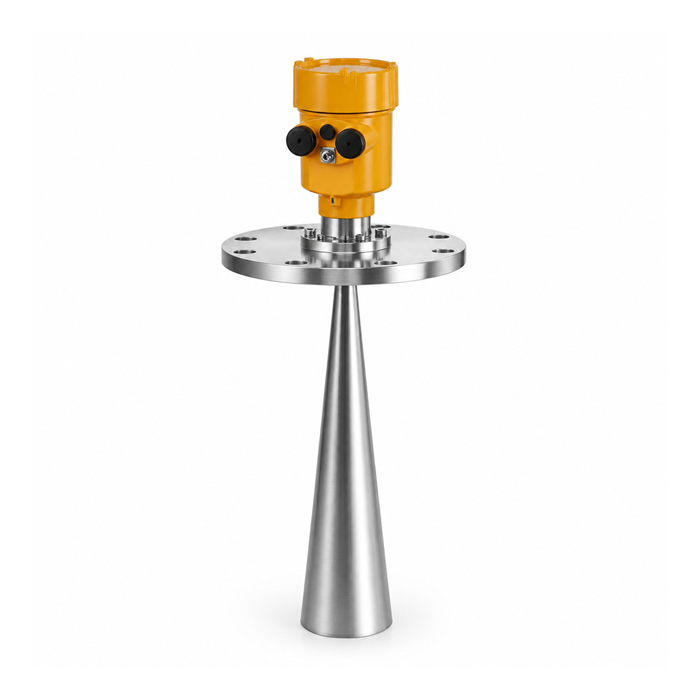
The Error Terms an Installed Radar Loop Accumulates
The table below lists the typical contributions to an installed radar level measurement accuracy budget. The magnitudes are typical engineering reference values for a 12 m liquid span and must be confirmed against the current data sheet and nameplate before use. The condition column states when each term grows or shrinks.
| Error term | Typical magnitude | Condition that changes it |
|---|---|---|
| Reference / datum offset | ±3 mm | Residual only, after any standoff is measured and removed in scaling |
| Mounting tilt | ±7 mm at 12 m | Beam 2° off vertical; error = R(1/cos θ − 1) |
| Vapour permittivity shift | ±12 mm at 12 m | Vapour at 2 bar gauge, n ≈ 1.001 |
| Temperature drift | ±7.2 mm at 12 m | 30 °C housing swing, e.g. 20 °C to 50 °C |
| Strapping-table interpolation | ±2 mm at 12 m | Table breakpoints coarser than 100 mm |
| PLC scaling resolution | ±0.2 mm at 12 m | 16-bit conversion over 0–12 m |
| Datasheet reference | ±5 mm | As quoted by manufacturer |
The values above are illustrative engineering references for a worked example. Confirm each against the current product data sheet and the installed nameplate before quoting an acceptance limit.
How Mounting, Tilt and Reference Shift Enter the Budget
The reference offset starts at the moment the flange is seated. The transmitter measures distance from its own antenna reference plane, which is rarely the same point the plant drawings call "empty". A 0.3 m stilling-well standoff or a 50 mm adapter changes the zero without changing the sensor. That part is a fixed offset, not random noise: measure it once with a tape and remove it in the scaling. What stays in the budget is only the residual uncertainty of that measurement, a few millimetres, not the 300 mm itself.
Tilt is a geometric term. Radar level measurement accuracy loses more to a misaligned beam than to the sensor itself. A radar beam aimed 2° away from vertical still returns a strong echo, but the extra path length at a 10 m range adds roughly 6 mm of apparent level, and about 12 mm at 20 m. On the 12 m span used here that is 7 mm. Because the term grows linearly with range and approximately with the square of the tilt angle at small angles, the alignment check belongs in the budget rather than in the commissioning notes. A universal flange or a verified plumb reference removes most of this term before it is ever counted, and the saving is largest on the tallest vessels in the fleet.
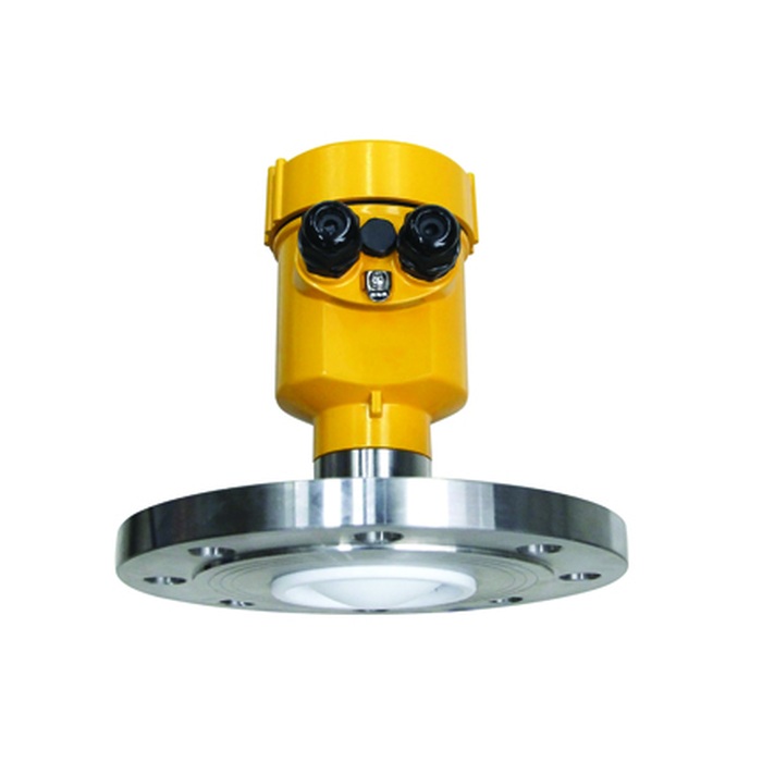
Vapour Permittivity and Temperature Drift as Added Terms
The gas above the liquid is not always air. In pressurised or cryogenic service the vapour has a permittivity above 1.0, and the radar pulse travels slightly slower through it than through a vacuum. Over a 12 m path a vapour refractive index of 1.001 adds 12 mm of distance error if it is ignored, because the error is the path length multiplied by (n − 1). The error scales with both path length and pressure: at 2 bar gauge the refractive index of nitrogen or hydrocarbon vapour sits near 1.001, and at 10 bar it approaches 1.005, which would put the same 12 m span out by 60 mm. This is the term most often missed when a tank that read correctly at atmosphere starts drifting after it is pressurised, because the sensor itself has not changed.
Temperature drift is the slow term. Most radar electronics are compensated, but the residual drift is still on the order of 0.02% of span per 10 °C of housing temperature change. Across a 30 °C housing swing on a 12 m span that is about 7 mm, small in a single reading but real across a tank farm where dozens of instruments sit at different solar exposures. Record the housing temperature at the time of the acceptance test so the term can be re-opened later if a dispute arises about a specific tank.
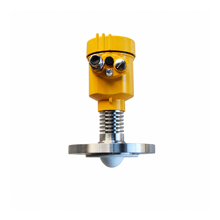
A Worked RSS Synthesis for a 12 m Span
A useful RSS calculation combines uncertainty contributions expressed on a consistent standard-uncertainty basis, with correlations assessed. It does not combine arbitrary maximum-error bounds into a guaranteed accuracy limit. The worked synthesis below treats the assumed site numbers as independent standard-uncertainty contributions solely to illustrate the arithmetic; it is not METRAVON measured field data.
Illustrative calculation, assumed site values:
- Datasheet reference: 5 mm
- Datum offset: 3 mm
- Tilt at 12 m: 7 mm
- Vapour shift: 12 mm
- Temperature drift: 7.2 mm
- Strapping-table interpolation: 2 mm
- PLC rounding: 0.2 mm
RSS = √(5² + 3² + 7² + 12² + 7.2² + 2² + 0.2²) RSS = √(25 + 9 + 49 + 144 + 51.84 + 4 + 0.04) = √282.88 ≈ 17 mm
Result: if the listed numbers are assumed independent standard-uncertainty contributions in millimetres, their RSS is about 17 mm. This is a combined standard uncertainty, not automatically a guaranteed ±17 mm error bound or a release acceptance limit. Convert actual specifications to a consistent uncertainty basis, correct known biases, assess correlations and state any coverage factor and decision rule before using the result for acceptance.
When the Budget Fails and How to Record the Limit
An error budget assumes the instrument is tracking a real surface. It stops being useful when the echo itself is invalid, because no arithmetic on clean terms will recover a reading that is not there. If the signal quality sits unchanged at the same low value across a known level change, if the level is pinned at full scale during a verified empty tank, or if the trace shows a stable peak at a fixed height regardless of the actual liquid, the fault is in the sensor, the mounting or the process, not in the accuracy chain. In those cases the correct action is to localise the fault through the echo trace and the installation record, then re-run the budget only after a valid echo is restored.
A budget is also the wrong tool for a tank whose level is genuinely discontinuous, such as a violently boiling surface or a tank with internal pipework that produces a stronger reflection than the liquid. There the dominant error is structural and must be solved by stilling well, guided wave or a different measurement path before any accuracy number is meaningful. The budget should then be written into the commissioning file as a single signed limit with its component terms attached, so a later reading that falls outside it can be traced to a specific contribution rather than reopened from scratch.

FAQ
Q1. Is datasheet accuracy the same as installed accuracy?
No. Installed measurement performance must be assessed under the actual conditions, including datum, tilt, vapour, drift and receiving-system scaling. The example RSS is about 17 mm only when its inputs are assumed independent standard-uncertainty contributions. It is not directly comparable with a ±5 mm datasheet error limit on a different basis, and it is not automatically a guaranteed installed acceptance limit. Agree the uncertainty basis and decision rule before sign-off.
Q2. Why use root-sum-square instead of adding the errors?
RSS combines uncertainty components expressed on a consistent standard-uncertainty basis when their correlations have been assessed. Independence is not guaranteed merely because components have different names. A linear sum can bound simultaneous worst-case contributions; a coverage factor and the agreed decision rule are needed when uncertainty is used for acceptance.
Q3. Which term usually dominates an installed radar budget?
The vapour permittivity shift is the largest term in pressurised or cryogenic tanks, reaching about 12 mm on a 12 m span at 2 bar gauge. On atmospheric tanks the datum offset and tilt usually lead. Identify the dominant term first, because reducing it gives the biggest margin.
Q4. Does tilt error grow with tank height?
Yes. A fixed 2° beam tilt adds roughly 6 mm at a 10 m range and about 12 mm at 20 m, because the extra path scales with distance. Verify vertical alignment with a plumb reference or universal flange before counting the tilt term as zero.
Q5. Can PLC rounding really matter at 12 m?
Barely. A 16-bit conversion over a 0–12 m span resolves about 0.2 mm per count, far smaller than the other terms. It matters only on very short spans or high-resolution custody duties, where the rounding term should still be listed so the budget stays complete.
Q6. When should I abandon the budget and start fault-finding?
Abandon it when the echo is invalid: signal quality at its floor, a full-scale reading on a confirmed empty tank, or a fixed peak independent of liquid level. Those are sensor, mounting or process faults, not accuracy-chain terms, and must be fixed through the echo trace first.
SUMMARY
Radar level measurement performance in service requires an installed error and uncertainty assessment. On the illustrative 12 m span, the listed contributions give an RSS of about 17 mm if treated as independent standard uncertainties; that result is not automatically a ±17 mm guaranteed error bound. Build the assessment from verified site values, correct known biases, assess correlations and agree the coverage and acceptance decision rule. Start fault-finding instead when the echo itself is invalid.
Talk to a METRAVON engineer about this application
If you are preparing a tank acceptance test, send us the vessel height, operating pressure, vapour type and the reference plane on your drawing. Our engineers will review the site contributions, their uncertainty basis and correlations, and the acceptance decision rule before recommending which term needs the tightest control.