Chinese
 Spanish
 Russian
 Portuguese
 French
 German
 Indonesian
 Thai
 Vietnamese
 Arabic
 Italian
 Turkish
 Polish
 Japanese


Building a two-wire level transmitter loop budget before installation prevents the common field failure of a level loop that works on the bench but drops out at the far end of a long cable. A two-wire level transmitter draws all its power from the same 4–20 mA loop that carries its signal, so the available voltage at the instrument is whatever the supply delivers after the cable, any safety barrier and the receiver load have taken their share. Treating the 24 V supply as "always enough" is the usual reason a level loop works on the bench and fails in the field.
What a Two-Wire Loop Actually Powers
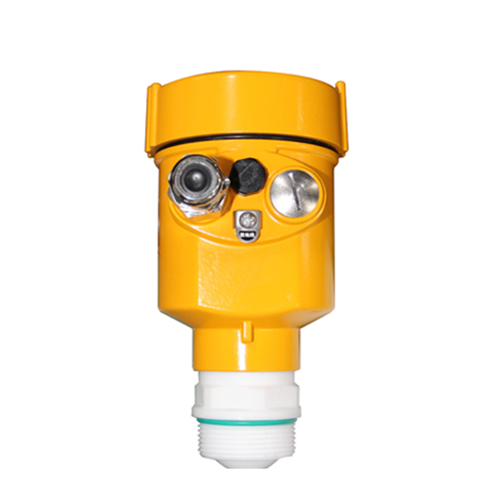
The two-wire level transmitter loop budget starts with the fact that the instrument is a variable resistor inside a current loop. The control system supplies a fixed loop voltage, typically 24 V DC, and the transmitter regulates its own current between 4 mA and 20 mA to represent the level. Because the same two conductors carry power and signal, every ohm of resistance in the path steals voltage that the transmitter needs to keep regulating. The instrument has a minimum operating voltage, often around 11 V, below which it drops out of range or stops communicating.
The loop also has to satisfy the HART signalling requirement. HART superimposes a low-amplitude digital signal on the analogue current, and that signal needs a minimum load resistance, usually 230–250 Ω, across the loop to develop a readable voltage swing. A receiver with a low input impedance, or a multiplexed input card, may need an external 250 Ω resistor added at the controller end before HART will work at all.
Drawing Up the Loop Voltage Budget
The two-wire level transmitter loop budget is a simple subtraction: the supply voltage must exceed the sum of the transmitter minimum, the cable drop at 20 mA, the barrier drop and the load drop. The table shows a typical 24 V DC example. All entries are illustrative engineering references and must be checked against the ordered instrument's nameplate and the barrier certificate before use.
| Budget item | Voltage drop | Condition that changes it |
|---|---|---|
| Transmitter minimum | 11 V | Steady-state, from nameplate |
| Receiver / HART load | 5 V | 250 Ω at 20 mA |
| Intrinsic safety barrier | 2 V | Typical barrier, verify certificate |
| Cable and start-up reserve | 6 V | 24 V minus the three fixed drops; 2 V held for inrush, 4 V available to the cable |
These are assumed values for a worked example, not METRAVON field data. Confirm the transmitter minimum, barrier drop and receiver impedance from the delivered documents before applying the result.
Separating Start-Up Surge From Steady-State Current
A two-wire level transmitter loop budget is often built only at the 20 mA steady state, but the transmitter can draw a higher inrush current when it first powers up, before the microprocessor settles. If the cable is already near its voltage limit at 20 mA, the start-up surge can pull the transmitter below its minimum and leave it in a reset loop that clears only when the level signal is re-applied. The fix is to reserve margin for the surge, not just the regulated 20 mA.
The safe practice is to size the cable for the worst current the instrument declares in its start-up specification, then re-check the 20 mA case. Where the surge figure is not published, leave at least 2 V of unallocated headroom in the budget rather than committing the last volt to cable length. This single reserve prevents a large class of "works after a power blink, then hangs" field complaints.
A Worked Cable-Length Calculation From the Budget
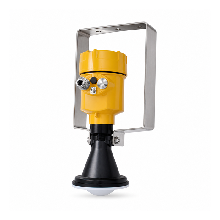
The two-wire level transmitter loop budget turns the leftover voltage directly into a maximum cable length. Of the remaining 6 V, 2 V is held back for start-up surge, so 4 V is the voltage the cable is allowed to drop at 20 mA. Using that figure we can solve directly for the run length. The example is a calculation method with assumed values, not a measured METRAVON result.
Illustrative calculation, assumed site values:
Voltage left after fixed drops: 6 V
Start-up reserve held back: 2 V
Available cable voltage: 4 V
Loop current: 20 mA = 0.020 A
Cable resistance allowed: 4 V / 0.020 A = 200 Ω
Cable: 1.5 mm² copper, ≈ 12.1 Ω/km per conductor
Loop uses two conductors: ≈ 24.2 Ω/km
Maximum loop length = 200 Ω / 24.2 Ω/km ≈ 8.3 km
Result: with these assumed values a 1.5 mm² pair could run about 8 km and still hold 20 mA with the inrush reserve intact. Committing the whole 6 V to cable instead would give 300 Ω and 12.4 km, but leaves nothing for start-up — that is the number to avoid quoting as a usable run.
Boundary condition: voltage stops being the binding limit long before this length. HART needs total loop capacitance below roughly 0.2 µF, and 1.5 mm² cable reaches that near 2 km, so the practical HART limit is about a quarter of the voltage-only figure. Thicker cable (2.5 mm², ≈ 14.5 Ω/km loop) raises the voltage ceiling without moving the capacitance ceiling, while a 1.0 mm² pair (≈ 36 Ω/km loop) shortens the voltage limit to about 5.5 km. Size the cable by both limits, and replace the assumed resistance and voltage with verified site figures before quoting a cable limit.

HART Load and Multi-Drop Limits
A two-wire level transmitter loop budget must also reserve margin for the HART load, not only for the analogue drop. HART communication deserves its own line because it fails quietly. If the total loop resistance falls below about 230 Ω, the HART modem at the transmitter cannot impose its signal and the handheld or asset system reports no device, even though the 4–20 mA reading looks fine. The common remedy is a 250 Ω resistor at the receiver, but that resistor also consumes 5 V at 20 mA, which is exactly the term already counted in the budget above.
Multi-drop HART, where several transmitters share one pair, changes the rule again: each addressable device still needs the loop to stay above its minimum voltage, and the summed cable length now serves every device on the segment. Plan the cable budget for the device furthest from the supply, then confirm the nearest device does not exceed its own maximum loop voltage, which is commonly 30 V or 36 V and must be read from the nameplate.

When the Loop Budget Says No
The two-wire level transmitter loop budget shows when a device should not be used as specified. If the required cable run exceeds the length the budget allows, do not simply raise the supply voltage past the instrument maximum or remove the safety barrier to recover margin, because both actions break other rules. The honest outcomes are to use a larger cable cross-section, move the power supply closer, or select a transmitter with a lower minimum operating voltage.
Some two-wire transmitters support a local display within their declared power budget. Heating, switching or other auxiliary functions require the power and output capability documented for the ordered device; they are not ruled out or permitted solely by wire count. If the required function exceeds that capability, assess a separately powered or three-/four-wire arrangement.
FAQ
Q1. Why does a 24 V supply not give 24 V at the transmitter?
A two-wire level transmitter loop budget explains why the supply voltage is not what the transmitter sees. Because the cable, any intrinsic safety barrier and the receiver load each drop voltage, and the transmitter itself needs a minimum to regulate. On a long run the cable alone can consume several volts at 20 mA, so build the budget before assuming the instrument sees the supply voltage.
Q2. What does the 250 Ω resistor actually do?
It develops the HART digital signal as a voltage across the loop; without at least about 230 Ω the HART modem cannot impose its communication. At 20 mA it also drops 5 V, which must be counted in the voltage budget or HART may work but the loop margin disappears.
Q3. Can I raise the supply to 36 V to reach a longer cable?
Only if every component, including any barrier and hazardous-area arrangement, accepts the proposed supply conditions. At a fixed loop current, a passive resistance has the same I × R voltage drop when supply voltage is raised. Recalculate terminal voltage, component ratings and any barrier limits rather than assuming the load drop itself increases.
Q4. Why does my transmitter reset after a power blink?
A start-up surge can pull the loop below the transmitter minimum if the cable is already near its limit at 20 mA. Reserve margin for inrush, not just steady-state current, or the device cycles through reset until conditions improve.
Q5. Is RS485 Modbus easier on power than 4–20 mA?
It is different, not easier. A two-wire 4–20 mA loop powers the instrument from the loop, while an RS485 Modbus level transmitter usually needs a separate local supply but avoids analogue load drops. Choose by what the controller input and the site power layout support.
Q6. When should I abandon two-wire and pick another wiring?
Reassess the arrangement when the required cable exceeds the verified loop budget or the required auxiliary functions exceed the device's declared power capability. A local display alone does not rule out a two-wire transmitter. Consider suitable cable, supply location or a separately powered device while retaining all required protection.
SUMMARY
A two-wire level transmitter loop budget sets the usable cable: from a 24 V DC supply, after an 11 V instrument minimum, a 5 V HART load and a 2 V barrier, 6 V remains, of which 2 V is held for start-up so 4 V reaches the cable — on assumed 1.5 mm² values about 8 km at 20 mA, and nearer 2 km before HART capacitance bites. Confirm the delivered nameplate figures, then size the cable or change the wiring method if the budget says no.
Talk to a METRAVON engineer about this application
Send us your loop supply voltage, the cable cross-section and length to the controller, and whether a safety barrier or HART handheld is in the path, and we will return a loop voltage budget with the maximum usable cable length for your transmitter model.