Chinese
 Spanish
 Russian
 Portuguese
 French
 German
 Indonesian
 Thai
 Vietnamese
 Arabic
 Italian
 Turkish
 Polish
 Japanese


A radar level meter mounted on an outdoor tank or a tall silo is one of the most exposed devices in the plant when a thunderstorm passes. The damage is rarely the direct strike; it is the surge that travels down the power and signal cables and arrives at the transmitter faster than any disconnect can act. Effective protection is a coordination problem between two stages of surge protective devices and a low, verified earth path, not a single component bolted at the instrument.
What a surge actually does to a level transmitter
A nearby lightning event injects a fast, high-current pulse, typically modelled as an 8/20 µs waveform, into the power line, the signal loop or the earth around the structure. The pulse seeks the path of least impedance to ground and will pass through the transmitter front-end if that is the easier route than a protective device. The result is a destroyed power supply, a burnt communication driver or a failed analogue input, usually at a cost far above the protector itself because the tank is then unmonitored. The transmitter enclosure and antenna do not need to be hit directly; an induced surge on a 50 m cable run is enough. Protection therefore has to act on the cables, which means both the 24 V DC power and the 4–20 mA or RS485 signal path need their own protective device sized to the energy they may carry.
Two-stage SPD coordination in one arrangement
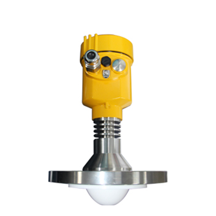
A single surge protector at the instrument is rarely enough, because the device-rated protector cannot absorb the full energy of a major surge and survive. The usual arrangement places a high-energy stage at the panel or cabinet where the cable enters, then a lower-clamping fine stage at the transmitter. The two must be coordinated so the first stage diverts most of the current and leaves the second stage a survivable burden. The table sets typical reference ratings; confirm the actual device data sheet before purchase.
| Stage | Location | Discharge capacity | Clamping voltage Up |
|---|---|---|---|
| 1 (coarse) | panel / cabinet entry | 20 kA (8/20 µs) | 1.5 kV |
| 2 (fine) | at transmitter | 3 kA (8/20 µs) | 0.6 kV |
The signal path needs its own coordinated pair, because a surge arriving on the 4–20 mA loop bypasses a power-only protector and still destroys the transmitter. Both stages must share the same earth reference, or the fine stage clamps to a floating node and protects nothing.
A signal protector also inserts series resistance into the 4–20 mA loop. At 20 mA a 24 V supply allows 1200 Ω of total loop; with the transmitter needing 12 V at its terminals, that leaves about 350 Ω beyond the 250 Ω sense resistor — two 10 Ω protectors still fit. A loop already near its limit, or one powered at 12 V, must count that resistance before the devices are chosen, not after the first low reading.
Worked residual-voltage example
For an illustrative resistive earth-potential-rise estimate, 1.5 kA through an assumed 4 Ω gives 6.0 kV relative to a remote reference. Adding an assumed 0.6 kV clamp gives a possible 6.6 kV stress only for a specified port and return/reference topology; it is not automatically the voltage between every protected input terminal. The expression R < (1.5 − 0.6) kV / 1.5 kA = 0.6 Ω is a boundary for that simplified assumed circuit, not a universal earthing acceptance requirement. Verify the actual surge modes, bonding impedances, lead inductance, SPD coordination and equipment port withstand.
The connecting lead contributes a voltage the data sheet clamp does not include. An 8/20 µs pulse of 1.5 kA rises at roughly 190 A/µs, and 1 m of bonding conductor carries about 1 µH, so the inductive drop is V = L · di/dt ≈ 1 µH × 190 A/µs = 190 V; at 5 m the same run adds about 0.95 kV, more than the stage-2 clamp. Input (rise rate and lead length) → conversion (L · di/dt) → result (190 V per metre of lead). Boundary: this assumes a straight run with no shared return; a short route to the equipotential bar beats a lower clamp on paper.
Earth resistance and why it sets the clamping floor
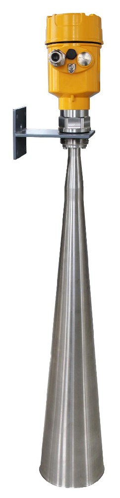
An SPD limits voltage relative to its specified reference terminals. Protection depends on equipotential bonding, conductor routing, surge-current distribution and the equipment ports being protected. A low-frequency earth-electrode resistance measurement is useful evidence but does not alone describe high-frequency surge impedance or prove protection. Use the project's approved earthing and lightning-protection design and verify lead lengths, continuity, electrode condition and SPD coordination; 4 Ω and 1 Ω are not universal acceptance criteria for every instrument installation.
When surge protection will not save the instrument

A fine instrument SPD alone is not a complete direct-lightning protection system. Where lightning current can enter, assess the external lightning-protection system, equipotential bonding and correctly coordinated lightning-current-rated devices, including Type 1 protection where required by the design. No arrangement gives an unconditional guarantee against every strike. Protection also fails when the signal line is left unprotected while only the power is protected. It fails again when the earth conductor is open or missing, or when a protector has already absorbed several strikes and silently expired. A long unscreened cable acts as an antenna and feeds induced voltage straight to the terminal. A protector mounted on a long, thin earth lead performs little better than none, because the lead inductance and resistance dominate the clamp. For a tank in a region with more than a few storm days per year, the structure should also sit inside a properly designed lightning-protection zone, with the instrument as the last, fine stage rather than the only one.
Post-storm acceptance checklist and records

After a thunderstorm season, the protection has to be proven still working, not assumed. The checklist below turns that into a recorded test; keep the sheet with the commissioning file so the next technician can see what was verified and when.
| Check item | Test method | Pass criterion |
|---|---|---|
| Earth resistance | fall-of-potential at electrode | Meets the approved site earthing and bonding design; record measured value and test conditions |
| Stage-1 SPD status | indicator / resistance check | green, not tripped |
| Stage-2 SPD status | indicator at transmitter | within service window |
| Bonding conductor | visual + continuity to earth bar | < 0.1 Ω, no corrosion |
| Signal-line protector | loop continuity through device | intact, no open circuit |
| Records | dated sheet filed | all items signed off |
Any failed item is a scheduled replacement before the next storm season, because a protector that has quietly expired gives no warning during clear weather and fails exactly when it is needed.
FAQ
Q1. Why do I need two surge protectors, not one?
Because a single device at the transmitter cannot absorb a major surge and survive while still clamping low. A coarse stage at the cable entry diverts most of the current, and a fine stage at the instrument clamps what remains. Without coordination the fine stage sees the full energy and fails, leaving the transmitter exposed to the next event.
Q2. How low must the earth resistance be?
Use the earth-resistance and bonding criteria set by the approved site design. The simplified 4 Ω example illustrates earth potential rise relative to a remote reference, not a universal device-terminal voltage or pass limit. Verify electrode test results together with bonding continuity, conductor layout, surge modes and coordinated SPD characteristics.
Q3. Does protecting the power line protect the signal too?
No. A surge on the 4–20 mA or RS485 loop bypasses a power-only protector and still destroys the transmitter. The signal path needs its own coordinated protector sharing the same earth reference, or the fine stage clamps to a floating node and protects nothing during the event.
Q4. How do I know a surge protector has failed?
Most devices carry a status indicator or a measurable change in pass resistance; a tripped or degraded unit must be replaced. A protector gives no warning in clear weather, so it should be checked on a fixed schedule after each storm season rather than only when the instrument fails.
Q5. Can a direct lightning strike be survived?
A fine SPD alone does not address direct lightning current. Protection for exposed structures requires an assessed external lightning-protection and bonding arrangement, with lightning-current-rated and coordinated SPDs where the design requires them. It reduces risk within declared limits and cannot guarantee survival of every strike.
Q6. Why use a short, thick earth lead?
Lead inductance and resistance dominate the clamp during the fast surge, so a long thin earth lead can make a good protector perform like none. Keep the bonding conductor short and generously sized, bonded to the earth bar at the entry, so the stage-2 clamp references a stable, low-impedance earth.
SUMMARY
Radar surge protection requires coordinated power and signal protection, equipotential bonding and an earthing arrangement verified against the site design. The simplified I × R calculation illustrates one possible earth-potential rise; it does not establish a universal 1 Ω acceptance target or the voltage across every input port. Supply the cable routes, signal types and protection requirements so the actual surge modes, SPD ratings and test criteria can be assessed.
Talk to a METRAVON engineer about this application
If you are protecting level meters on outdoor tanks or tall silos, send us the cable routes, the power and signal types at each transmitter, and your local annual storm-day count. Our engineers will specify the two-stage SPD arrangement and the earth-resistance target for your installation, with a post-storm check list.