


 Chinese
 Spanish
 Russian
 Portuguese
 French
 German
 Indonesian
 Thai
 Vietnamese
 Arabic
 Italian
 Turkish
 Polish
 Japanese


METRAVON Millimeter-Wave Radar Chips: Operating Principle, Architecture and Technical Features
Millimeter-wave radar chips generate and receive the radio-frequency signals used by some ranging instruments. For a level-measurement purchase, the useful distinction is between the RF component and the finished transmitter: component features do not establish the installed measuring range, process compatibility or level accuracy.
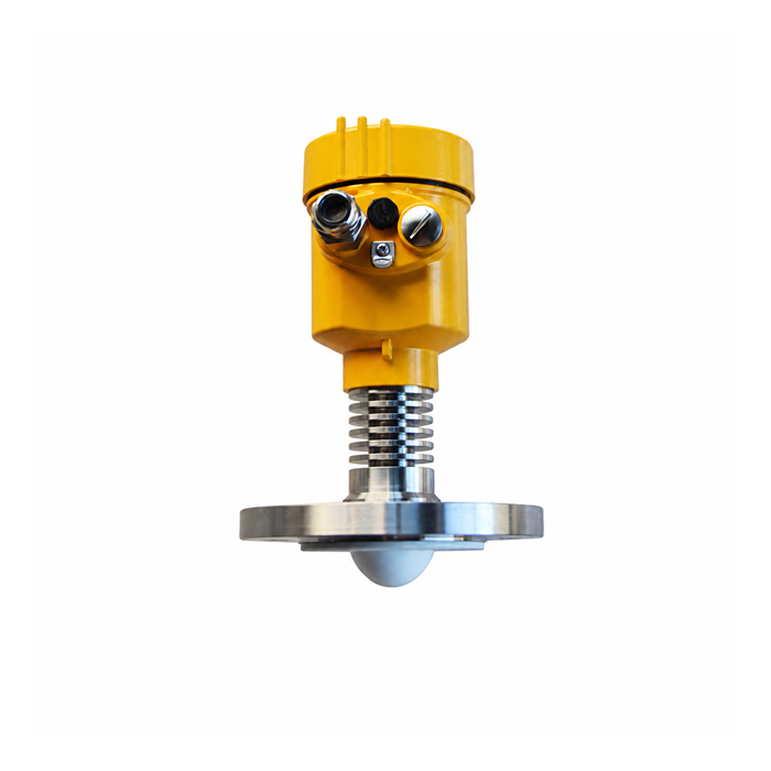
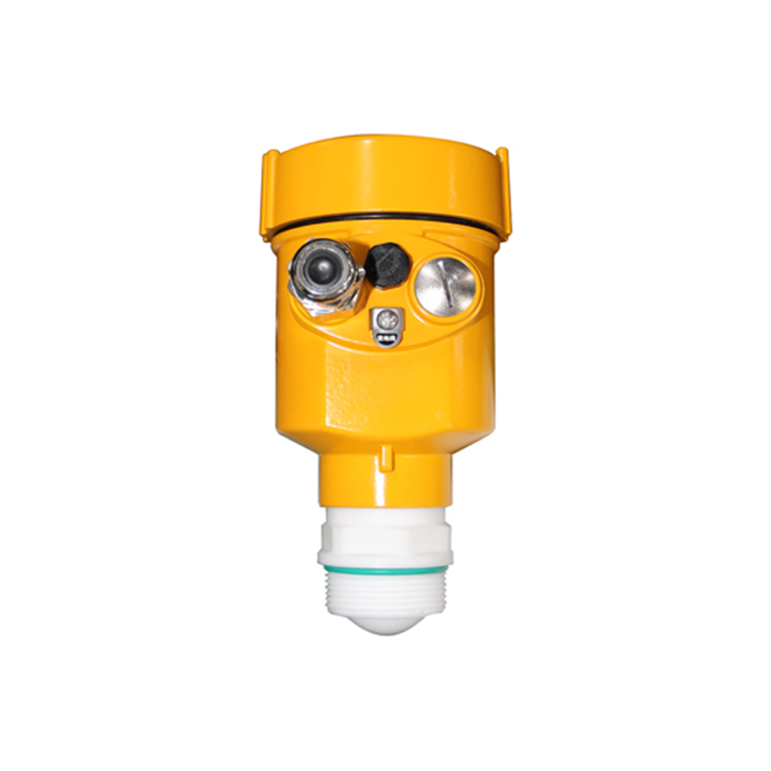
A design may integrate the RF front end, ADC, processor and parts of the detection software, or distribute those functions across components. METRAVON MV-RD11 and MV-RD14 are complete liquid-level instruments. Their product names and operating frequency do not identify an internal chip part number or prove that raw sample data are accessible.
What Is Millimeter-Wave Radar?
Millimeter waves generally refer to electromagnetic waves in the approximate frequency range of 30 GHz to 300 GHz, corresponding to wavelengths of roughly 1 mm to 10 mm.
Practical radar systems use only selected portions of this spectrum. Common examples include 60 GHz, 77 GHz, 79 GHz and the approximately 80 GHz band widely used in industrial level measurement.
Two concepts should be separated clearly: the center operating frequency defines the radar band, while the effective modulation bandwidth is one of the key factors affecting FMCW range resolution.
Millimeter-Wave Radar Is an Active Sensing Technology
Radar actively transmits electromagnetic energy and analyzes the signal reflected from a target.
The target does not need to carry a transmitter. As long as it reflects enough electromagnetic energy back toward the radar, the system can detect it.
How Does FMCW Radar Measure Distance?
Many modern millimeter-wave radars use FMCW, or Frequency Modulated Continuous Wave, technology.
The radar continuously transmits a chirp whose frequency changes with time. After the signal reflects from a target and returns to the receiver, the propagation delay creates a frequency difference between the delayed echo and the current transmitted signal.
A mixer combines the received echo with a transmit reference to form a beat signal. For an ideal stationary target and linear chirp, beat frequency is proportional to chirp slope multiplied by round-trip delay. Motion, leakage, noise and multiple reflectors complicate the real estimate; a finished instrument must select the intended surface, not just detect a spectral peak.
FMCW radar therefore uses propagation delay indirectly through frequency comparison rather than relying only on a direct high-speed time-of-flight counter.
What Blocks Are Typically Integrated in a Millimeter-Wave Radar Chip?
Generates stable and controllable millimeter-wave frequencies and chirp signals.
Boosts the RF signal before it is delivered to the transmitting antenna.
Amplifies weak reflected signals while minimizing additional receiver noise.
Combines the received echo with a reference signal to generate baseband or intermediate-frequency information.
Converts analog baseband signals into digital samples for further processing.
Performs FFT processing, filtering, target detection, tracking and data output.
Why Does Higher Frequency Support More Compact Antennas?
For a comparable antenna aperture, shorter wavelength can reduce angular beam width. Alternatively, a smaller aperture may achieve a similar beam width at higher frequency. The actual antenna pattern and installation drawing still govern clearance; frequency alone is not a beam-angle specification.
In industrial level radar, this means that relatively small process connections can still support concentrated measuring beams that are easier to position away from vessel walls, agitators, pipes and other internals.
Does Higher Radar Frequency Automatically Mean Higher Accuracy?
Actual ranging performance depends on several factors, including:
- Effective modulation bandwidth;
- Signal-to-noise ratio;
- RF front-end noise;
- Antenna design;
- ADC performance;
- System calibration;
- Target-detection algorithms.
A radar operating at 80 GHz is not automatically more accurate than every 60 GHz or lower-frequency design.
How Does Radar Measure Velocity and Angle?
Moving targets produce a Doppler effect. By comparing phase and frequency changes across multiple chirps, the radar can estimate radial velocity.
Angle measurement usually requires multiple receiving antennas arranged as an array. By comparing phase differences between channels, the system can estimate the direction of arrival.
Angular resolution depends on the array aperture, channel arrangement, calibration and processing. A single level value does not establish that the instrument measures angle, radial velocity or a three-dimensional surface. Confirm those functions explicitly if the project requires them.
Semiconductor platform and component availability
Semiconductor process, chip identity and long-term component availability require supplier documentation if they form part of the contract. They cannot be established from a transmitter photograph or its frequency band. For routine replacement planning, retain the complete model, hardware or firmware revision, approved configuration and service documentation.
Why Does Chip Performance Not Equal Complete Radar Performance?
The radar chip is only one part of the measurement system.
Final performance also depends on:
- Antenna design;
- PCB RF layout;
- Power-supply and EMC design;
- Housing and radome construction;
- Signal-processing algorithms;
- System calibration;
- Installation environment.
Two radar products built around similar RF silicon can therefore deliver very different field performance.
Why Millimeter-Wave Chips Matter in Industrial Level Radar
In an FMCW level instrument, RF circuitry supports chirp generation and echo reception. The device specification must establish how that circuitry, antenna, processing and calibration perform together. Do not infer the chirp bandwidth or semiconductor architecture of a METRAVON model from an industry description of an 80 GHz design.
Field performance, however, depends on the complete combination of RF front end, antenna, dynamic range and level-echo processing.
For an integrator, useful evidence includes the usable measuring span, response and fault behavior, supported output, diagnostic access and the conditions of the stated error. Those items help define a testable instrument supply; a list of internal processing blocks does not.
From RF architecture to a transmitter specification
| Term | Meaning | Purchase check |
|---|---|---|
| Carrier frequency | Position of the operating band | Obtain the actual antenna and model data |
| Chirp bandwidth | Contributes to ideal target separation | Do not substitute it for an accuracy specification |
| RF and ADC performance | Influences usable echo information | Check the complete instrument under required conditions |
| Display increment | Smallest displayed numerical step | Do not treat extra digits as lower measurement error |
| Processed output | Value and status sent to the host | Confirm units, timing, validity and documented interface |
Range resolution is the ability to distinguish nearby targets in distance. Measurement accuracy concerns agreement with a reference under stated conditions; repeatability concerns repeated measurements under the same conditions. These are different claims, and a fine display increment proves none of them.
Evaluate how the finished device identifies the surface before changing filtering or requesting replacement electronics. Radar reliability checks at the vessel
Questions about components and instrument data
Q1. Does a named radar chip prove the accuracy of a level transmitter?
No. A chip identity does not establish the antenna pattern, process isolation, calibration or target-selection behavior of the finished instrument. Compare the complete transmitter specification and test it in the required operating states. If component identity is a contractual requirement, obtain explicit supplier confirmation rather than inferring it from the frequency or enclosure.
Q2. Should an integrator request ADC samples or a processed level value?
Request what the receiving system actually needs. A PLC control loop normally requires a documented engineering value and status; algorithm development may require raw or intermediate data that a process transmitter does not expose. Confirm access, format, timing and support before purchase. An RS485 output does not by itself provide raw RF or ADC data.
Specify the delivered data and documentation
For an instrument order, separate three deliverables: the measured value and status, the diagnostics available to the user, and any component or firmware information required by contract. Resolve missing documentation before selecting the receiving hardware or accepting a substitute.
For a complete level instrument, provide the vessel, medium, nearest and farthest surfaces, nozzle and process limits. Add the host interface and required diagnostic access. If chip identity, raw samples or firmware support is contractual, list those requirements separately for written confirmation. Discuss the complete radar instrument requirement
