


 Chinese
 Spanish
 Russian
 Portuguese
 French
 German
 Indonesian
 Thai
 Vietnamese
 Arabic
 Italian
 Turkish
 Polish
 Japanese


METRAVON Radar Level Transmitter Reliability: Key Factors and Practical Improvements
A radar level transmitter can have excellent laboratory specifications and still perform poorly in the field if the installation geometry, process conditions or configuration are unsuitable. Long-term reliability is therefore determined by the complete application, not by the accuracy line on a datasheet alone.
The most important question is whether the true product-surface echo remains easy to identify throughout the full operating range. Mounting position, filling flow, agitators, foam, low-dielectric liquids, condensation, buildup and vessel internals can all change that echo environment.
1. Mounting Position Is the First Reliability Check
Free-space radar measures the distance to the product surface by transmitting electromagnetic waves and receiving the reflected signal. Any strong reflector inside the beam can compete with the true level echo.
Typical fixed reflectors include:
- Filling pipes and nozzles;
- Agitator blades and shafts;
- Heating coils;
- Internal beams and supports;
- Thermowells;
- Long or poorly designed mounting nozzles.
There is no universal wall-clearance ratio that works for every vessel. The practical objective is to keep the main measuring beam clear of strong fixed structures over the entire level range.
2. Filling Streams Can Create Temporary Measurement Problems
A radar installed directly above a filling stream may see splashing, dust, a moving material stream or a rapidly changing product surface. These conditions can produce temporary echo changes even when the instrument is healthy.
Where possible, position the radar away from the direct filling path. This is especially important for bulk solids and vessels with high-velocity liquid filling.
3. Agitators Affect Both the Surface and the Echo Pattern
An agitator can create waves, vortices and foam, while rotating blades may periodically enter the radar beam. The result can be cyclic fluctuation or intermittent target switching.
Typical improvements include:
- Moving the radar away from the blade path;
- Using a narrower beam where appropriate;
- Checking the echo curve during agitation;
- Applying damping only after the correct target is being tracked.
Damping can smooth a valid signal. It cannot correct a radar that is tracking the wrong reflector.
4. Foam Can Weaken or Change the Measured Target
Foam does not have one universal effect on radar. Depending on thickness, liquid content, bubble structure and dielectric properties, the radar may detect the foam surface, partially penetrate the foam, or lose part of the liquid-surface echo.
For foaming processes, define whether the control objective is the foam surface or the actual liquid level before selecting and configuring the instrument.
5. Low-Dielectric Liquids Need More Echo Margin
Some oils, hydrocarbons and solvents reflect less radar energy than water. The risk of weak echo increases when low dielectric properties are combined with long measuring distance, foam, a strong tank-bottom reflection or complex vessel internals.
These applications should be evaluated as a complete system. Software filtering alone cannot compensate for insufficient signal margin.
6. Why Low Level Can Be More Difficult
With some low-dielectric liquids, part of the transmitted energy can pass through the product surface and continue toward the tank bottom. A metal bottom may then create a strong fixed reflection.
At low level, the true product echo and tank-bottom echo can move close together. Symptoms may include target switching, low-level jumps or intermittent loss of echo. Echo-curve analysis is more useful than simply moving the zero point upward.
7. Condensation and Buildup Still Matter on Non-Contact Radar
Non-contact does not mean maintenance-free. Water film, oil, dust, crystallization or process deposits on the antenna or process isolation surface can alter the near-field echo environment and reduce the useful product echo.
Typical signs include:
- New strong near-field echoes;
- Gradually weakening product echo;
- Unexpected high-level indication;
- Intermittent loss of echo.
8. A Fixed Offset Is Often a Reference or Scaling Problem
If the radar value follows the real level correctly but remains consistently offset, check the reference height, empty/full configuration, radar reference plane and PLC/DCS scaling before changing echo parameters.
Use a reliable independent measurement to verify the true distance. If the measured distance is correct but the displayed level is wrong, the problem is usually in the conversion from distance to engineering level.
9. Local Display Correct, Control Room Wrong
If the local radar display is correct but the PLC or DCS value is not, focus on the signal chain:
- Actual 4–20mA loop current;
- Analog input range;
- 4mA and 20mA engineering values;
- Engineering units;
- Barriers, isolators and wiring.
10. When a Stilling Well or Guided Wave Radar May Help
A stilling well can be useful in selected liquid vessels by creating a more controlled free-space radar path. It is not a universal cure, and poor dimensions, internal discontinuities or heavy buildup can create additional problems.
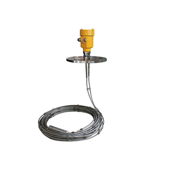
Guided wave radar may be considered for selected low-dielectric liquids, small vessels, interface measurement or applications where a defined probe path is useful. Probe coating, corrosion and mechanical loading must also be considered.
11. Use False-Echo Suppression Only After the Real Level Is Known
False-echo mapping is useful for unavoidable fixed structures such as beams, supports or permanent pipework. Before learning fixed echoes, confirm the true product level and save the original echo curve.
If the mounting position is fundamentally poor, correct the mechanical installation before relying on software suppression.
12. Problems That Configuration Alone Usually Cannot Fix
| Condition | Better Response |
|---|---|
| Main beam directly hits a structural beam | Change mounting geometry or beam selection |
| Heavy antenna buildup | Clean, improve process isolation or use an approved purge arrangement |
| Low-dielectric liquid over a difficult long range | Reassess instrument and antenna selection |
| Filling stream crosses the beam | Move the measurement point |
| PLC scaling error | Correct the control-system configuration |
13. Reliability Checklist
- Confirm the beam avoids major fixed structures;
- Check both maximum and minimum process level;
- Verify antenna condition and process-side cleanliness;
- Confirm reference height and empty/full configuration;
- Check PLC/DCS scaling independently;
- Save a normal echo curve after commissioning.
14. What Reliable Radar Performance Really Depends On
Reliable radar measurement depends on keeping the real product echo strong, stable and easy to identify. Installation geometry, process behavior and material properties matter more than adding more filtering after the problem appears.
For difficult vessels, good application data and a saved commissioning echo curve are among the most useful tools for maintaining long-term measurement stability.
