


 Chinese
 Spanish
 Russian
 Portuguese
 French
 German
 Indonesian
 Thai
 Vietnamese
 Arabic
 Italian
 Turkish
 Polish
 Japanese


Level Measurement Technology Comparison: Radar vs Ultrasonic vs Guided Wave
Select level measurement from the medium, vessel geometry, pressure, temperature, foam, required uncertainty and maintenance access. Non-contact radar, guided-wave radar, ultrasonic and differential pressure each have suitable applications and distinct limitations; no single technology is best for every tank.
Comparison of level measurement methods
| Technology | Useful applications | Main selection checks |
|---|---|---|
| 80 GHz non-contact radar | Focused measurement in liquid tanks and suitable solids silos | Actual range, antenna, foam, deposits and process ratings |
| 26 GHz non-contact radar | Suitable liquid and solids applications | Antenna size, beam, nozzle and model performance |
| Guided-wave radar | Suitable foam, low-reflectivity and interface duties | Probe coating, forces, transition zones and dielectric conditions |
| Ultrasonic | Suitable atmospheric tanks and channels | Gas, temperature gradients, foam, blind zone and mounting |
| Differential pressure | Liquid level where density and process connections are managed | Density, pressure compensation, seals and impulse lines |
| Capacitance | Suitable continuous or point-level duties | Dielectric changes, probe coating and calibration |
| Float or magnetic gauge | Suitable local indication and alarm duties | Density, moving parts, deposits and process compatibility |
Compare the required range, installed accuracy, process ratings, mounting requirements and cost for the actual candidate models.
Non-contact radar, 80 GHz
An FMCW radar sweeps a specified frequency band and derives distance from the received signal. The carrier band, sweep bandwidth and processing are model-specific; not every industrial 80 GHz unit uses exactly 76-81 GHz.
A focused non-contact radar is useful where tank walls or internals restrict the measuring path, or where contact with the product is undesirable. Check nozzle compatibility and the required process and hygienic ratings.
Limitations to check: dense or wet foam, antenna deposits, weak product echoes, unsuitable nozzle geometry and process ratings. Purpose-designed 80 GHz solids radars can operate in dusty, long-range applications; frequency alone is not a dust or range limit.
Typical applications: chemical reactors, food and beverage vessels, pharmaceutical tanks, small day tanks, water and wastewater, OEM skids.
Non-contact radar, 26 GHz
Either pulsed radar or FMCW at 26 GHz, usually with a horn antenna.
Evaluate when the antenna, range, process limits, signal margin and quotation suit the vessel. A 26 GHz unit is not inherently the only long-range or dusty-service option.
For a 10° antenna, the geometric footprint at 20 m is about 3.5 m. Check wall clearance, nozzle geometry and the available surface echo in narrow tanks or low-reflectivity service.
Typical applications: cement and minerals silos, large storage tanks, water reservoirs.
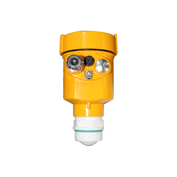
Guided-wave radar (TDR)
A low-energy pulse travels down a rod or cable and reflects at the impedance change caused by the product surface. Time of flight gives distance.
Evaluate guided wave for suitable foaming, low-reflectivity or confined applications, subject to probe selection, process compatibility, mechanical loads and upper and lower transition zones.
Probe coating, bridging and forces from mixing or moving solids can limit guided-wave measurement. The probe and process connection must also meet the cleaning and material requirements.
Typical applications: foam-generating reactors, liquefied gases, small dosing vessels, interface measurement in separators.
Ultrasonic
An ultrasonic transducer measures acoustic round-trip time. The conversion needs the sound speed along the gas path. Check the model's temperature compensation and its limits; one temperature reading may not represent a strong gradient or changing gas composition.
Ultrasonic instruments can be economical for clean, open or vented tanks with a suitable measuring distance and stable gas conditions.
Foam, steam, dust, vacuum, temperature gradients and surface disturbance can weaken or distort the acoustic echo.
Typical applications: water tanks, sumps, simple chemical storage, wastewater channels.
Differential pressure
Level is inferred from hydrostatic head: delta-p = density x g x height for the appropriate reference arrangement. In a closed vessel, account for vapor-space pressure and the effects of wet legs or remote seals. Changing density changes the conversion even when the pressure measurement itself is correct.
Differential pressure is an option for liquid vessels where density and the pressure connections can be managed reliably.
Limitations to check: changing density, blocked impulse lines, wet-leg or seal-temperature effects and material compatibility. Vacuum service requires a suitable DP, seal and installation design; it does not automatically rule out DP measurement.
Typical applications: boiler feedwater, clean process liquids, high-pressure vessels.
Capacitance
A capacitance system senses the change between its probe and a suitable counter-electrode, which may be a conductive tank wall or a separate reference. Confirm the arrangement for nonconductive vessels and the effects of product conductivity, dielectric changes and coating.
Capacitance is an option for suitable continuous or point-level duties where the probe arrangement and dielectric behaviour are understood.
Probe coating and changes in dielectric properties can affect the response, so calibration must match the medium and operating conditions.
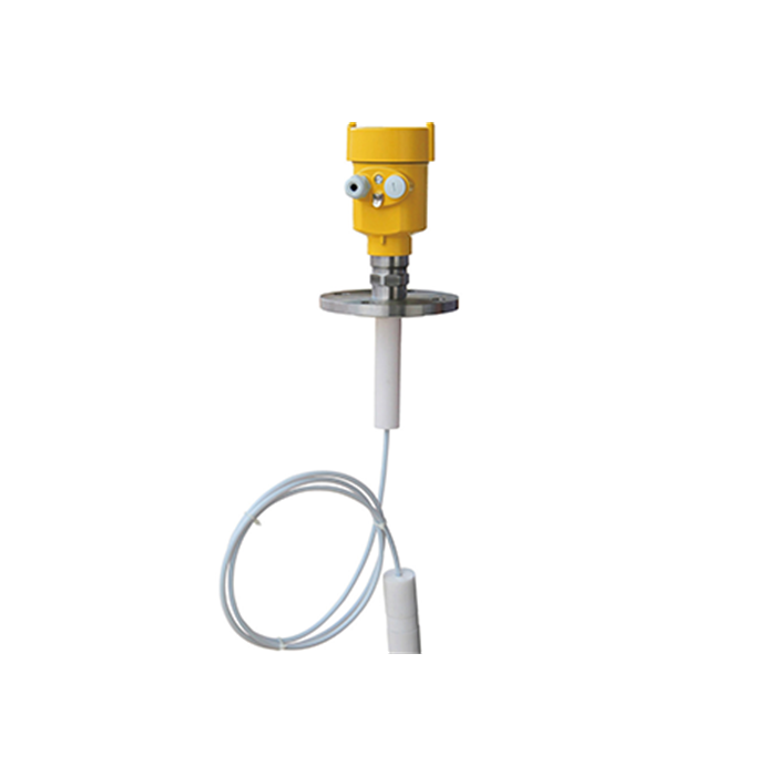
Float and magnetic level gauges
A float follows the surface; a magnetic coupling transfers the position to an indicator or a reed switch chain.
Float and magnetic gauges provide local indication or threshold signals in suitable clean liquids, including applications that require an unpowered visual indicator.
Check float density matching, moving parts, deposits and access for inspection before using a float or magnetic gauge in viscous or fouling service.
Five questions for the application specification
- Is the tank pressurised or under vacuum? Check the selected instrument's pressure rating and gas-path limits. Conventional gas-path ultrasound is unsuitable for vacuum; modest positive pressure is not by itself a universal exclusion if the model is rated for it.
- Is there foam or heavy surface disturbance? Compare target visibility and fouling risks for the actual radar or probe; trial difficult service.
- What are the product's dielectric properties over the operating range? For weak returns, compare the actual radar sensitivity, antenna, distance and guided-probe options. No single dielectric-constant cutoff selects the technology for every vessel.
- How wide is the tank relative to its height? Calculate beam clearance and check internals and nozzle geometry. A narrow-beam radar or guided probe may be a candidate, but neither removes its model-specific installation constraints.
- What total installed uncertainty, response time and approval does the application require? Define these from the inventory, process, custody or safety duty instead of assigning universal millimetre targets.
Details to include in the purchase specification
- Compare purchase cost with installation, isolation, inspection, cleaning, validation and downtime requirements. Use site maintenance evidence rather than assumed service intervals for each technology.
- Provide nozzle bore, length and antenna position with the vessel drawing; these dimensions can determine whether the proposed radar arrangement is suitable.
- State the measurement reference, required range and verification method when specifying an accuracy such as ±3 mm.
- Specify the required output and diagnostics. A 4-20 mA transmitter with HART, a Modbus instrument and an independent point-level switch serve different integration needs.
- For difficult radar service, ask what application evidence, echo diagnostics and commissioning support are available for the proposed configuration.
Total cost of ownership over five years
A five-year cost comparison should use supplier quotations, installation estimates and the site's maintenance records. Include the following cost categories:
| Cost element | Evidence to collect |
|---|---|
| Instrument and approvals | Comparable supplier quotations for the required configuration |
| Installation | Nozzle, probe, chamber, isolation and wiring work |
| Cleaning and inspection | Site maintenance history and accessibility |
| Verification and calibration | Approved intervals, reference method and labour |
| Downtime | Actual isolation, cleaning and restart requirements |
| Five-year total | Use project quantities and uncertainty; no universal technology multiplier |
There is no universal cost ranking. A clean, vented water sump may suit ultrasonic measurement; a difficult process can justify a different instrument. Calculate the complete installed lifecycle cost for the actual duty.
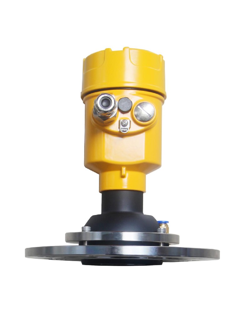
Point level versus continuous level
Continuous transmitters report quantity or level, whereas point switches report a threshold condition. Safety-related overfill protection may use an approved continuous sensor or a point device; the required independence, diagnostics, proof testing and final action follow the risk assessment and safety design.
Interface measurement
Measuring an oil-water interface requires more than finding the upper surface. Guided-wave radar can be a candidate when the upper layer transmits sufficient energy and the two media produce a usable dielectric contrast. Verify upper-layer thickness, composition, emulsion, probe design and supported interface functions. Do not assume a free-space level transmitter or every guided-wave model reports both surface and interface.
FAQ
Q1. Which is more accurate, radar or ultrasonic?
Compare candidate model specifications with the required installed uncertainty, not just the technology name. For example, 0.25% of a 10 m span is 25 mm, but first check whether the datasheet defines error as a percentage of span, range or reading. Include mounting, reference and process effects in field acceptance.
Q2. Can radar replace differential pressure on a pressurised tank?
Sometimes, provided the radar is rated for the pressure, temperature, medium and connection. It avoids converting liquid head using density, but still needs a suitable signal path and verified performance in the vapor space. A change also affects isolation, maintenance, safety functions and the acceptance procedure; it is not only a sensor substitution.
Q3. Is guided-wave radar better than non-contact radar?
Guided wave may help where a free-space echo is unreliable, but it introduces a wetted probe and mechanical constraints. Coating, bridging, probe forces and the transition zones can rule it out. For foam or low-reflectivity liquids, compare the actual probe design and application evidence rather than assuming guided wave always performs better.
Q4. Does 80 GHz radar always cost more than 26 GHz?
Frequency does not establish price. Compare quotations for equivalent process connections, materials, approvals, outputs and service scope. Include installation and maintenance costs; a cheaper instrument can require more nozzle work or cleaning access, while a higher initial price does not prove better suitability.
Q5. Which requirements govern custody-transfer measurement?
Select a system with the approvals and uncertainty required for the product and jurisdiction. Radar or servo gauging may be candidates, but the sensor is only part of the quantity-measurement chain. Tank calibration, temperature, density and traceability requirements must be established before treating the reading as a custody-transfer quantity.
Q6. Do I need SIL certification?
If the measurement forms part of a safety instrumented function, the safety requirements define the target integrity and acceptable device evidence. A transmitter certificate alone does not establish the achieved integrity of the sensor, logic solver and final element together. For indication-only duty, do not specify SIL simply as a substitute for an accuracy requirement.
A technology recommendation needs the medium, vessel geometry, process conditions, required uncertainty and control-system interface. Request a technology recommendation
Related reading: Radar Level Transmitter Troubleshooting: 9 Faults and How to Fix Them | Level Measurement in Foam: When Radar Works and When It Does Not
