


 Chinese
 Spanish
 Russian
 Portuguese
 French
 German
 Indonesian
 Thai
 Vietnamese
 Arabic
 Italian
 Turkish
 Polish
 Japanese


Radar Level Transmitter Dead Zone (Blocking Distance): How to Calculate and Avoid It
A radar level transmitter dead zone or blocking distance is a model-defined near-range restriction referenced to a specified measurement plane. It may reflect antenna behaviour, signal processing or a configurable exclusion zone. Confirm the exact reference, antenna and process conditions; do not assign a universal blind distance from frequency alone.
Calculating the measurable level range
Let E be the height of the documented radar reference above the chosen zero level, Dmin the permitted minimum distance including the approved safety margin, and Dmax the permitted maximum distance. Then the measurable liquid levels satisfy E - Dmax <= h <= E - Dmin, limited further by the vessel operating range.
Include nozzle geometry when establishing E and checking the installation, but do not subtract nozzle length automatically from tank height. Raising the reference can increase high-level clearance; a long or narrow nozzle can also create interference or impose separate mounting limits.
Worked example:
- Example: the vessel zero-to-roof height is 4.0 m and the radar reference is 0.35 m above the roof, so E = 4.35 m.
- Assume the complete antenna and nozzle configuration is approved by the manufacturer.
- Assume the chosen model permits a 0.30 m minimum reference-to-surface distance.
- Add a 0.05 m project margin, giving Dmin = 0.35 m.
- The upper measurable level is E - Dmin = 4.35 - 0.35 = 4.00 m. If the model also covers the empty distance, the geometric operating range can include 0-4.0 m; nozzle echo behaviour still needs commissioning checks.
Set 4-20 mA lower and upper values to the validated operating levels, not to an automatic tank-height-minus-nozzle formula. Prove that the whole mapped span is measurable and verify the configured saturation and failure behaviour.
Near-range information to obtain for the exact configuration
| Configuration | Information required |
|---|---|
| Free-space lens or horn | Documented reference plane and minimum permitted surface distance |
| Nozzle-mounted radar | Antenna-specific nozzle bore, length, protrusion and interference limits |
| Guided-wave rod or cable | Upper and lower transition zones for the actual medium and probe |
| Process or hygienic seal | Additional restrictions and temperature/pressure configuration |
| Alarm configuration | Validated high-level distance, response margin and fault action |
Use the reference plane and permitted distances specified for the selected antenna, medium and mounting arrangement.
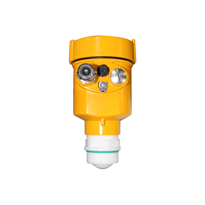
Four ways to recover the required high-level coverage
1. Raise the mounting flange
Moving the documented reference upward can place the required high level farther from it. However, an added standpipe may introduce interference; shortening a problematic nozzle may improve echo quality but also moves the reference closer to the liquid. Recalculate both geometry and mounting compatibility.
2. Choose an antenna with a shorter near field
Compare the specified minimum distances of the actual candidate configurations. If two approved arrangements share the same reference and one permits a 0.25 m minimum distance instead of 0.50 m, it can extend the accessible high level by 0.25 m, subject to operating and alarm margins.
3. Compare guided-wave transition zones
Guided-wave probes have upper transition zones and usually lower transition or end zones. Their size depends on probe type, medium and configuration; do not assume 20-100 mm or guaranteed full-height measurement.
4. Mount in a standpipe or chamber
A suitably designed chamber may move the reference and change the accessible range. Check process connections, equalisation, hydraulic response, deposits, transition zones and any pressure or steam compensation. It does not automatically remove near-range restrictions.
When the dead zone becomes a safety issue
If the required high or high-high level lies inside the instrument restriction, the measurement cannot be relied on to detect it. Check the complete demand point, response time, alarm handling and proof-test procedure, not simply whether an indicator can display a full tank.
Two rules:
- Check the distance from the documented reference plane to the high-high alarm level, including the required response and process margins.
- Where risk assessment requires independent overfill protection, design an appropriate independent sensor, logic and final action. A point switch, continuous radar or another technology may be suitable when approved for that function; technology choice alone does not establish independence or SIL suitability.
Dead zone versus other near-range effects
| Effect | Meaning | What to verify |
|---|---|---|
| Near-range restriction | A specified limit, exclusion or reduced-accuracy region | Reference plane, model limits and actual surface distance |
| Nozzle reflection | A possible fixed return near the antenna | Mounting drawing and selected echo; peak position alone is not proof |
| Antenna response or deposits | May change the close-range trace | Approved diagnostics and safe inspection of the antenna |
| Output saturation or fault signaling | Configured current behavior, not a universal 20.5 or 22 mA value | Device status, range mapping and specified alarm currents |
Distinguish physical limits, configurable exclusions, interference and analogue saturation. Some can be improved through approved mounting or settings, but none should be bypassed without checking operation throughout the required range.
Commissioning checklist for the top of the tank
- Measure the nozzle length and write it on the drawing.
- Establish the reference height E and model-specific permitted minimum and maximum distances.
- Map the analogue output to the validated operating levels and confirm units, direction and failure signalling.
- Place high and high-high demand levels within the validated range, with response and process safety margins.
- Verify the highest permitted test level using an approved procedure and independent reference. Do not deliberately overfill or enter a protection demand condition without authorization. Document any untested upper range and the evidence still needed before acceptance.
- Retain the reference dimensions, range values and test results with the loop documentation.
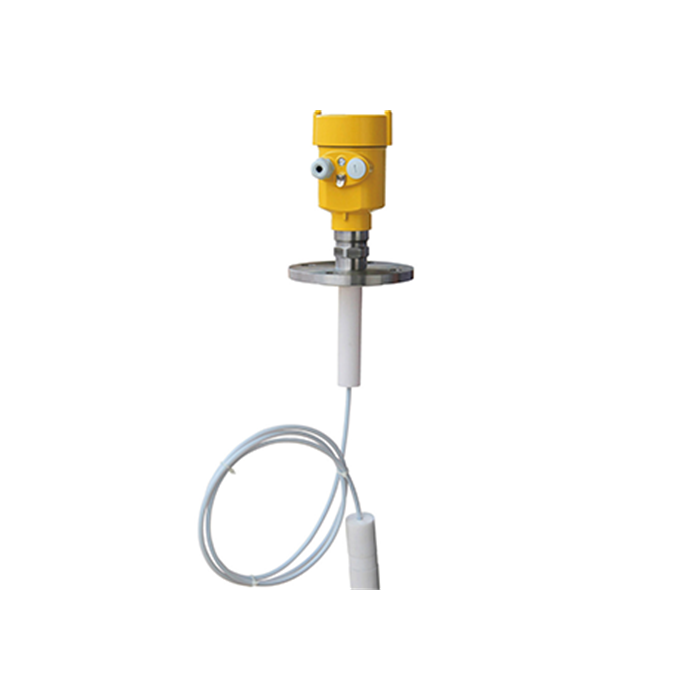
Dead zone in interface and dual-level measurement
A separator may require both total liquid level and the interface between two liquids. A conventional free-space level instrument does not automatically provide an interface value. A guided-wave instrument may support both measurements only with a suitable probe, media and configured interface function; a short near-range specification alone does not establish suitability.
For interface measurement, confirm that the upper liquid is sufficiently transmissive, the dielectric contrast is adequate, and layer thickness and both transition zones meet the selected instrument requirements. Referencing a probe from below is not a generic remedy.
Small-tank example: 800 mm day tank
Consider an illustrative 800 mm vessel with a radar reference 200 mm above the roof: E = 1000 mm. The high-level limit is E minus the specified minimum distance and safety margin, capped by the vessel operating limit. Long-nozzle echo effects must be checked separately.
| Illustrative configuration | Upper measurable level above vessel zero |
|---|---|
| E = 1000 mm, minimum distance 500 mm | 500 mm before extra safety margin |
| E = 1000 mm, minimum distance 250 mm | 750 mm before extra safety margin |
| E = 1000 mm, minimum distance 150 mm | 850 mm geometrically, capped by the 800 mm vessel limit |
| Any candidate | Also check permitted maximum distance, lower transition zones and nozzle compatibility |
Assess reference height, permitted distances and nozzle compatibility together. Nozzle length must not be added automatically to the instrument's minimum measuring distance.
FAQ
Q1. Is dead zone the same as blind zone?
The terms may overlap, but their definitions can differ. Separate the specified minimum measuring distance, a configured exclusion zone and a reduced-accuracy region. Identify the reference plane for each limit in the selected manual; a value measured from the flange cannot be substituted for one referenced to the antenna without checking the geometry.
Q2. Can firmware remove the dead zone?
Do not assume so. An update may change supported processing or configuration, but the permitted measuring range still comes from documentation for the exact assembly and conditions. Back up settings and verify the new configuration before service. Reducing a software exclusion value does not by itself prove reliable near-range measurement.
Q3. Why does my transmitter read zero at high level?
Check actual reference-to-surface distance, local status, selected target, output variable and PLC scaling. A zero could be a configured fault or conversion error as well as a sensing problem. Compare the measurement chain before concluding that the surface has entered the near-range restriction or changing the blocking setting.
Q4. Do guided-wave probes have a dead zone?
Guided-wave instruments have model-dependent upper and lower transition regions, sometimes with reduced accuracy rather than the same behavior as a free-space exclusion zone. Check probe type, medium, mounting and any weight or end hardware. Validate both required endpoints; probe length is not automatically the usable measuring span.
Q5. Does a longer nozzle make the dead zone worse?
No universal one-to-one rule applies. A nozzle changes reference geometry and may add reflections or exceed antenna mounting limits. Raising the reference can improve high-level clearance while a narrow or long neck worsens echo behavior. Review those effects separately, then verify the selected arrangement over the required range.
Supply the zero-level datum, radar reference height, nozzle dimensions and required operating and alarm levels for a range review. Get a range calculation
Related reading: Radar Level Sensor Beam Angle: What It Is and How to Size It for Your Tank | Level Measurement Technology Comparison: Radar vs Ultrasonic vs Guided Wave
