


 Chinese
 Spanish
 Russian
 Portuguese
 French
 German
 Indonesian
 Thai
 Vietnamese
 Arabic
 Italian
 Turkish
 Polish
 Japanese


Radar Level Sensor Beam Angle: What It Is and How to Size It for Your Tank
Radar level sensor beam angle describes the antenna pattern using the convention stated in its datasheet, commonly a full angle at the half-power (-3 dB) contour. A focused beam may help avoid walls and internals, but frequency alone does not define the angle or prove a mounting location suitable.
Understanding the quoted beam angle
Beam angle is quoted as the full angle in most datasheets, not the half angle. At the edge of that cone the power is 3 dB below the centre — 50%. That is not "no signal", so a strong reflector just outside the nominal cone can still be detected. Practical installation rules therefore add margin.
Because the beam widens with distance, the footprint grows linearly:
Spot diameter (m) ≈ 2 × Distance (m) × tan(θ / 2)
Where θ is the full beam angle. A useful approximation for small angles: spot ≈ distance × angle in radians, which is why a 4° beam gives roughly 70 mm of spot per metre of range.
Spot size at real distances
| Full angle | Diameter at 10 m | Diameter at 20 m |
|---|---|---|
| 4 degrees | 0.70 m | 1.40 m |
| 6 degrees | 1.05 m | 2.10 m |
| 8 degrees | 1.40 m | 2.80 m |
| 10 degrees | 1.75 m | 3.50 m |
| 12 degrees | 2.10 m | 4.20 m |
At 10 m, the geometric diameter of an 8° beam is about 1.4 m. Allow additional clearance for mounting position, antenna characteristics and possible strong reflectors outside the nominal cone.
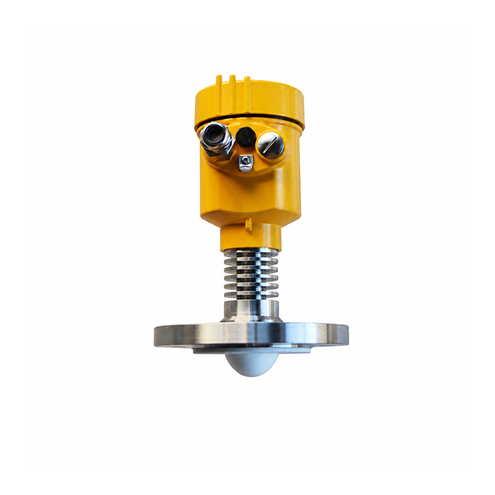
Applying the footprint to the vessel layout
Narrow tanks
At an 8 m distance, a 10° beam has a geometric footprint of about 1.40 m, whereas a 4° beam is about 0.56 m. In a 1 m diameter tank, the narrower cone gives more clearance, but installation quality still depends on offset, wall material, internals and antenna characteristics.
Standpipes and long nozzles
A long nozzle can introduce near-field and multiple reflections. Far-field beam geometry alone does not establish a permissible nozzle length: use the antenna-specific nozzle diameter, length, protrusion and surface-finish requirements from the installation manual.
Tanks with internals
Agitators, heating coils, baffles and ladders all sit somewhere in the cone. Narrow beams do not eliminate them, but they reduce the number of them the radar can see, and reduce the energy they return.
Foam and low-dielectric products
A narrow beam can improve separation of the surface from tank clutter. Performance on foam and low-reflectivity liquids also depends on dynamic range, antenna design and the medium; 80 GHz does not universally penetrate foam better than 26 GHz.
Nozzle dimensions and mounting clearance
- Select nozzle bore and length from the installation drawing for the exact antenna.
- Avoid unnecessary nozzle length and internal edges. Additional nozzle length does not have a universal one-to-one relationship with blocking distance.
- At the lowest operating level, compare the beam radius with the distance to the nearest wall and internal structure. Include the model-specific mounting clearance and margin; the nominal cone is not a boundary beyond which reflectors are invisible.
- Keep the measuring path clear of the inlet stream and the resulting surface disturbance.
- Avoid mounting directly above an agitator shaft, even if the blades are below the measuring range.
- For plastic or GRP vessels, assess possible reflections from structures outside the tank and follow the antenna mounting instructions. Do not add a metal flange or pipe as an assumed universal radio-frequency shield.
What a smaller beam angle does not fix
- Foam attenuation depends on thickness, liquid fraction, conductivity and bubble structure. Beam focusing does not remove these effects.
- Condensation on the antenna. A narrow beam cannot avoid a film on its own face.
- Very low dielectric constant in a tall tank. At 30 m, even a 4° beam is 2.1 m wide and the returning energy from an εr of 1.8 product may still be below the threshold.
Choosing between 26 GHz and 80 GHz on beam angle alone
| Situation | 26 GHz candidate | 80 GHz candidate |
|---|---|---|
| Narrow vessel | Check actual antenna beam and wall clearance | A smaller focused antenna can help |
| Long nozzle | Use approved bore, length and antenna position | Small beam does not waive nozzle limits |
| Dusty atmosphere | Assess deposits and signal margin | Solids-specific designs can suit severe dust |
| Long distance | Verify model range and reflectivity | Not inherently limited to 30 m |
| Foam | Test actual foam and liquid target | Not a universal foam-penetration advantage |
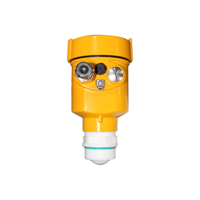
Sizing example: 100 mm nozzle on a 1.2 m tank
A 1.2 m diameter tank, 8 m tall, with a 100 mm bore nozzle 400 mm long. Which beam angle is acceptable?
- Clearance at the bottom. For a centered, vertical axis in a 1.2 m diameter tank at 8 m distance, the geometric limiting full angle is 2 x arctan(0.6/8), about 8.6 degrees, before any installation margin. An offset axis has less clearance to the nearest wall. A 4 degree beam leaves more geometric clearance in this simplified example.
- Nozzle check. The simple cone calculation gives about 28 mm at 0.4 m for a 4° beam, but this does not prove the nozzle is acceptable: the antenna near field and specified mounting drawing govern.
- The alternative. At 8 m, a 10° beam is approximately 1.40 m wide, exceeding the 1.2 m vessel diameter. This increases the risk of wall interactions at low level; it does not guarantee a false reading in every installation.
A 4° antenna provides more geometric clearance in this example. Confirm nozzle compatibility and signal quality over the required level range before selecting the instrument.
Checking clearance on an existing installation
- Measure the tank diameter and the distance from the flange to the lowest level you must measure.
- Calculate the footprint at that distance from the datasheet beam angle.
- Apply the installation clearance required for the actual radar, mounting offset, wall and internal structures rather than a universal 100 mm deduction.
- If the footprint exceeds the available clearance, check low-level curves for wall or multiple-path reflections.
- Possible changes include a narrower antenna or a compatible stilling arrangement. Raising the lowest measured level is acceptable only if it still meets the process requirement.
FAQ
Q1. Is beam angle measured at −3 dB or −6 dB?
Use the antenna convention stated in the datasheet. For the same pattern, a -6 dB contour is normally wider than its -3 dB contour, so angles with different definitions are not directly interchangeable. Neither contour is a hard boundary beyond which a metal reflector becomes invisible.
Q2. Can I calculate the footprint from the antenna diameter?
Aperture size and wavelength influence the beam, but antenna design and illumination also matter. A diameter-based estimate is not a mounting approval. Use the specified full angle and antenna drawing for the ordered configuration, then check near-field nozzle limits separately from the far-field footprint.
Q3. Does a narrower beam mean a longer range?
Not by itself. Compare the stated measuring range for the medium, return strength, antenna, receiver and installation. A focused beam can reduce clutter but does not guarantee a usable surface echo through foam, deposits or a difficult vapor space. Range and required clearance are separate checks.
Q4. What happens if the beam hits the tank wall?
A wall or internal structure may produce fixed or multiple-path echoes that interfere with tracking, especially when the surface return is weak. Compare traces at the affected levels with the vessel geometry. An overlap signals a risk to evaluate; it does not prove that every installation will report an incorrect value.
Q5. Is a stilling well a substitute for a narrow beam?
A compatible pipe or chamber may improve the measuring path, but its dimensions, openings, buildup risk and hydraulic response must suit the instrument and process. Check any required pipe configuration or compensation. Do not add a generic stilling well merely to avoid verifying the antenna and nozzle arrangement.
A mounting review needs the vessel diameter and height, nozzle bore and length, operating levels and locations of internals. Get a mounting review
Related reading: Radar Level Transmitter Dead Zone (Blocking Distance): How to Calculate and Avoid It | How to Read a Radar Level Echo Curve (And What Each Shape Means)
