


 Chinese
 Spanish
 Russian
 Portuguese
 French
 German
 Indonesian
 Thai
 Vietnamese
 Arabic
 Italian
 Turkish
 Polish
 Japanese


Radar Level False Echo: Causes, Suppression and When Mapping Fails
A radar level false echo is a reflection from something other than the intended product surface. It becomes a measurement problem when the target-selection logic follows it instead of the surface, not simply whenever it is the largest peak. Improve the mounting first; then use verified, device-specific suppression without masking the real measuring range.
Where false echoes come from
| Source | Distance behaviour | Check before suppression |
|---|---|---|
| Nozzle rim, flange bore | Fixed | Nozzle geometry and approved antenna position |
| Antenna face, condensate film | Fixed, very short | Antenna condition and near-range diagnostics |
| Weld seams, tank roof structure | Fixed | Measured distance to the structure |
| Ladder rungs, dip pipes | Fixed | Drawing and observed surface movement |
| Agitator shaft and blades | Fixed shaft, moving blades | Traces with recorded agitator state |
| Heating coils, baffles | Fixed | Locations relative to the measuring path |
| Multiple reflections (roof ↔ surface) | Moves with level | Movement and spacing of echoes during level changes |
| Vortex or splashing | Moves fast | Surface behavior and selected target |
Distinguish fixed structures from changing reflectors. Confirm the physical source and operating conditions before mapping; a stored suppression is not a permanent substitute for checking the echo curve after changes.
Method 1: remove the reflector
Mechanical changes can reduce unwanted reflections before they reach the receiver and are usually easiest to assess during vessel design.
- Shorten the nozzle where the mechanical design permits and use the antenna-specific mounting limits; added nozzle length is not automatically added blocking distance.
- If the approved antenna drawing calls for a smoother bore or altered edge, have the mechanical design reviewed before modification. Do not machine, weld or open a process connection without the required isolation and work authorization.
- Mount away from the inlet so the beam does not look at a falling stream.
- Avoid a measuring path obstructed by an agitator. A stilling arrangement is an option only if its dimensions, equalization, fouling risk and process connections are approved for the application.
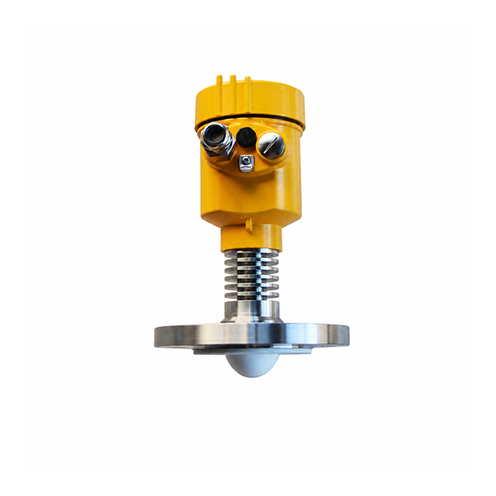
- Set antenna protrusion from the model-specific mounting drawing. A flush or protruding face is not suitable for every nozzle or antenna design.
Method 2: empty-tank mapping
False-echo mapping stores a suppression profile for verified obstructions. It changes how reflections are selected; it does not remove the physical reflector.
Procedure:
- If permitted, use an empty or sufficiently low-level vessel to expose the obstructions of interest. Define the verified surface position and the space that can safely be mapped; an unobserved region is not validated by the procedure.
- Clean the antenna by the approved method before mapping so that temporary deposits are not included in the suppression profile.
- Start the device-specific suppression procedure, enter the independently verified surface distance and set a safe mapping limit before that surface. Do not assume a universal scan duration or full-range sweep.
- Use the process state specified by the instrument procedure. Some agitator-related suppression requires blades to move through their positions. Do not stop or start equipment solely for mapping unless the process and safety arrangements permit it.
- Verify at safely accessible levels spanning the affected region and compare against an independent reference. Record untested conditions; successful checks at a few points do not prove behavior over every level and process state.
- Record settings, level and process conditions. After a mechanical change, review the trace and suppression profile; repeat the approved procedure only where needed and verify the result.
Do not map the real surface or an unidentified tank-bottom return. If interference appears only in a particular condition, investigate its geometry and follow the manufacturer-supported procedure for that condition; mapping a full tank blindly can suppress the valid target.
Method 3: threshold and echo tracking
Where supported, adjust the threshold within a defined distance window around a confirmed interfering reflection.
Use it when:
- the false echo is in a fixed, narrow distance band,
- you cannot empty the tank for mapping,
- the false reflector only appears in one process condition.
A global threshold increase may reject a weak real surface as well as the obstruction. Verify the full operating range and expected changes in product reflectivity.
Echo tracking uses the previous valid distance and other configured criteria to follow a target. It can reject short disturbances, but persistent interference still requires investigation.
Method 4: change the microwave path
If mechanical changes are impossible and mapping does not hold, change the antenna or the frequency:
- A narrower beam can reduce exposure to walls and internals if the new antenna also meets the process and mounting requirements.
- At a given frequency, a suitable larger aperture can provide a narrower beam or higher gain. Confirm the actual antenna pattern, process rating and nozzle limits rather than selecting by size alone.
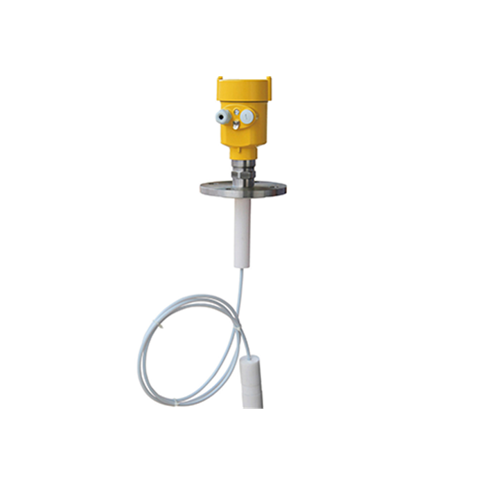
- Guided-wave radar confines propagation along a probe and can reduce free-space clutter, but nozzle reflections, launch echoes, probe contact, coating and end-zone effects still need evaluation.
- A compatible stilling well can limit exposure to internals and surface disturbance. Check its dimensions, venting, equalisation and buildup risk.
Diagnosing which method you need
| Observation | Possible cause | Next check |
|---|---|---|
| False echo at a constant short distance | Nozzle or antenna | Confirm nozzle and deposits; correct mounting before mapping |
| False echo at constant distance but further out | Tank internals | Verify the internal reflector and safe suppression limit |
| Echo appears only above a certain level | Roof or structure reflection | Capture traces across the affected levels before defining a window |
| Echo appears only during mixing | Blades or vortex | Compare blade positions and surface motion; review the measuring path |
| Echo appears after weeks of service | Buildup on antenna | Inspect safely; clean by the approved method and reassess the profile |
| False echo stronger than surface at long range | Weak surface echo | Check target strength and installation; compare suitable antenna or probe options |
A worked example
With a 12 m reference height, a fixed reflection 2.2 m below the reference corresponds to an indicated level of 9.8 m. If this value appears only at low actual levels, compare the reflection position with exposed internals on the drawing.
Confirm the obstruction and actual surface distance before suppressing the echo. Check that the suppression does not reject the real surface as it passes through the same distance; relocation may provide a more reliable measuring path.
Mapping a tank you cannot empty
If the tank cannot be emptied, limit the review to the space and operating conditions that can be checked safely.
- Map only the exposed space between the reference and a safe distance before the independently verified surface, using the actual model procedure. Never include the real product echo in the suppression.
- For level-dependent interference, capture curves and consult the device procedure. Do not create a suppression window at the actual product surface merely because the fault occurs there.
- Use a sister tank only as a comparison reference. Do not import a suppression curve as a validated solution: mounting offsets, welds, internals, antenna configuration and reference height must be checked on each installation.
Verifying that mapping worked
Verify the suppression against the selected target and an independent level reference:
- The previously reported false level has disappeared from the display.
- The diagnostic overlay shows the known interference being rejected while the real surface remains selected with adequate margin. Mapping does not necessarily reduce the raw physical reflection.
- The reading matches a manual measurement at low, mid and high level.
If interference returns, compare the operating state and antenna condition with the original record. Check for moving internals, new deposits and changed geometry rather than assuming the stored profile is still valid.
FAQ
Q1. Can a false echo be stronger than the real echo?
Yes. Metal internals may return more energy than a weak liquid surface. Compare the peak distance with the vessel drawing and an independent surface reference, then observe which echo moves with level. Do not raise a global threshold simply because an obstruction produces the largest peak.
Q2. Does mapping survive a firmware update?
Preservation depends on the device and the specific update procedure. Export the settings and suppression data where supported, and record the current version before maintenance. After an update, verify the configuration and selected target against a known level instead of assuming the stored curve is unchanged or still appropriate.
Q3. Why does my transmitter report a level higher than the tank can hold?
A closer false target is one possible cause, but first compare the selected distance, reference height, units and output scaling. An incorrect zero reference or PLC conversion can also produce an impossible displayed level. A near-range peak alone does not identify a nozzle fault; verify its position and the instrument status.
Q4. Can two radars in one tank interfere with each other?
Possible coupling depends on the exact instruments, modulation, frequency band, orientation and installation. Check the manufacturer's coexistence guidance. Where the process permits, compare operation with each instrument separately and retain the test conditions; do not switch off a required protection channel without an approved procedure.
Q5. Is a false echo always a fault?
Unwanted reflections can exist while the instrument correctly tracks the surface. They become a problem when they cause a wrong reading, loss of tracking or inadequate reliability under the operating conditions. Check selected target, status and response across the affected range rather than judging the installation by peak height alone.
Provide curves from both normal and faulty operation, together with the tank sketch and known surface distance. Send your data for review
Related reading: How to Read a Radar Level Echo Curve (And What Each Shape Means) | Radar Level Transmitter Troubleshooting: 9 Faults and How to Fix Them
