


 Chinese
 Spanish
 Russian
 Portuguese
 French
 German
 Indonesian
 Thai
 Vietnamese
 Arabic
 Italian
 Turkish
 Polish
 Japanese


Radar Level Measurement in Steam, Dust and Condensation: What Actually Works
Steam, dust and condensation are different measurement challenges. Evaluate vapour propagation, suspended droplets or particles, antenna deposits and the actual temperature and pressure. Purging can keep an antenna clear but does not remove the whole vapour space, and saturated high-pressure steam may require specialised compensation.
What each condition does to the signal
| Condition | What to investigate | Possible measurement effect |
|---|---|---|
| High-pressure saturated steam | Changing vapour dielectric properties and temperature/pressure | Propagation error; compensation may be required |
| Suspended droplets | Mist and wet surfaces | Attenuation or interference |
| Dust cloud | Particle type, moisture, concentration and range | Process-dependent signal loss or clutter |
| Condensation or deposits | Antenna face and nozzle | Weak surface echo or near-range interference |
| Other vapours | Composition, pressure and compatibility | Assess rated instrument and process conditions |
Steam, droplets and propagation effects
Dry water vapour, suspended droplets and a condensing antenna are not the same condition. At elevated steam pressure, changing vapour properties can affect radar propagation. Do not select a frequency or assume a steam error from the words saturated steam alone.
Options to assess for the actual process:
- Purged antenna. Use only a manufacturer-approved, process-compatible purge arrangement. Confirm gas, flow, pressure differential, backflow protection and process impact; there is no universal flow or differential-pressure setting.
- Thermal extension or remote electronics. Use the approved configuration to keep electronics within their ambient limit. An improvised extension is not a substitute for the required process seal or pressure rating.
- A compatible stilling well or bypass can improve geometry and surface conditions, but it does not remove steam or its propagation effects. Boiler-drum service requires an application-specific, rated measurement and protection design.
- Guided-wave radar can be useful in steam service, but high-pressure saturated steam may require vapour compensation. Check the probe, process rating, vessel arrangement and compensation capability rather than assuming steam is irrelevant.
Changing gain alone cannot remove condensation, droplets or an unsuitable measuring path. Diagnose these conditions before adjusting detection settings.
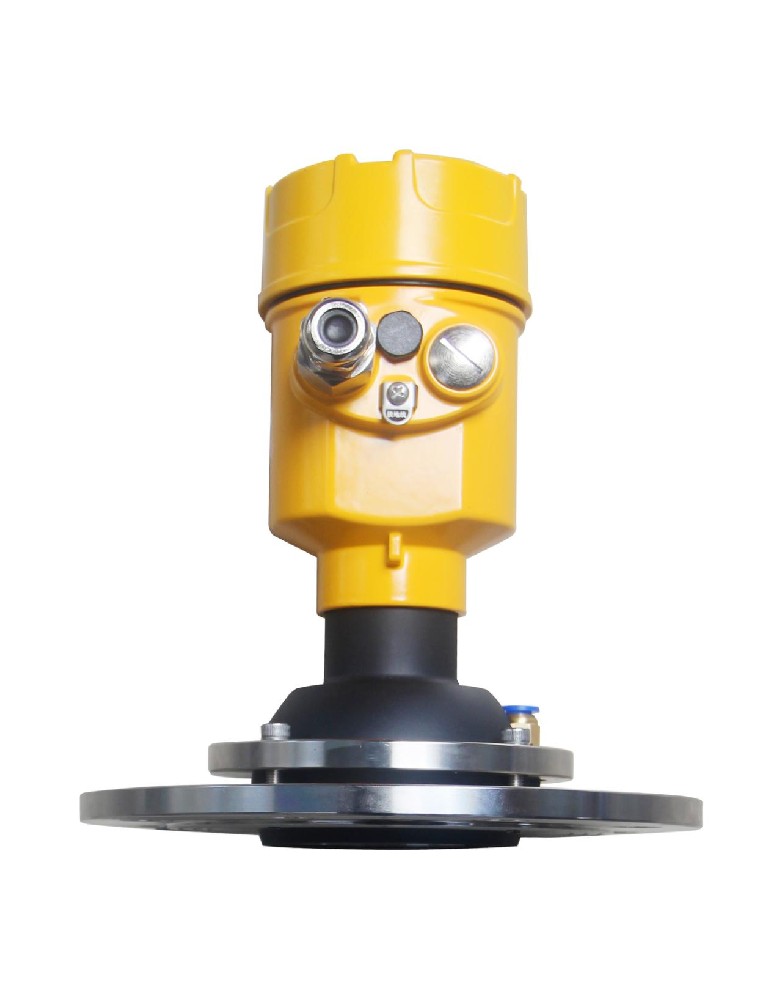
Dust: attenuation versus coating
Distinguish signal loss through the dust cloud from deposits on the antenna.
- Attenuation is loss along the outward and return paths. Compare measured signal quality during filling and settling; its magnitude depends on particles, moisture, concentration, range and radar configuration.
- Coating — dust settles on the antenna face, forming a layer that reflects energy before it leaves the antenna.
Frequency is only one consideration. Fine, dry dust is often compatible with radar, including purpose-designed 80 GHz solids instruments. Wet or heavily loaded dust and deposits can be harder; assess antenna, dynamic range, mounting and process together.
In cement and minerals silos, mount away from the filling stream and assess whether the antenna needs an approved cleaning connection. A cable probe is an alternative only after evaluating tensile loads, abrasion, bridging, contact with internals and maintenance access.
Condensation on the antenna
A water film can weaken the surface echo and produce a near-range reflection. Compare the antenna condition and selected distance before and after the vessel warms.
Assess the following measures for the selected instrument:
- A compatible antenna face may reduce wetting or simplify cleaning, but material alone does not guarantee that condensate or deposits will disappear. Check the actual assembly, chemical compatibility and observed behavior.
- Antenna heating requires an approved arrangement and a thermal assessment; power, process temperature and hazardous-area limits are configuration-specific.
- An approved dry-gas purge may help keep the antenna clear. Verify gas compatibility, moisture, flow, pressure and process effects; it does not remove the entire vapor space or guarantee that condensation cannot occur.
- Mounting orientation must follow the radar manual. Do not tilt a liquid-level radar merely to shed condensate if this compromises the surface reflection or required accuracy.
- Use approved thermal isolation or remote electronics where needed. It protects the instrument but does not necessarily prevent a condensing antenna face.
Damping cannot remove a film or recover an attenuated signal. Sensitivity and threshold changes require controlled verification after the physical cause is understood.
Selecting an antenna for the vapour space
| Candidate | Checks before selection |
|---|---|
| Free-space horn or lens radar | Process rating, beam clearance, dynamic range and antenna condition |
| Encapsulated or fluoropolymer-faced antenna | Full wetted-material compatibility and cleanability |
| Guided-wave probe | Steam compensation where needed; coating, mechanical loads and transition zones |
| Approved purge or heating assembly | Process compatibility, utility loss, backflow and hazardous-area limits |
| Ultrasonic | Gas composition, temperature gradients, mist and condensation can limit performance |
Purge design basics
An unsuitable purge can cool the antenna, disturb the process or introduce moisture. Gas quality, flow and pressure must therefore be specified together.
- Use only a purge gas approved for the process, often dry oil-free air or nitrogen where compatible. Combustible, oxygen-sensitive, moisture-reactive and hygienic processes require a specific review before introducing any gas.
- Specify the required purge flow and the pressure available at the process connection, including supply, regulator and backflow-protection requirements.
- Specify purge timing from the approved instrument and process design. Continuous or intermittent operation must be justified by deposit behavior, process effects, utility reliability and the response required when the purge fails.
- Provide the backflow protection, isolation and monitoring specified by the approved process and utility design. Do not assume a single generic check valve is sufficient for every pressure or hazardous medium.
- Use the manufacturer-approved purge connection and flow path. Confirm flow at the actual vessel pressure and permitted gas addition; an improvised gap around the antenna is not a substitute for the required assembly design.
Process information needed for selection
- Identify vacuum, normal and upset pressure. Any purge into a vacuum vessel changes the gas load and requires process, supply and pressure-control approval.
- Is the obstruction steam, dust, or condensation? Each points to a different antenna.
- Review whether a nozzle change is practical before specifying a different instrument.
- Check the product reflectivity and operating distance against the exact free-space or guided-wave model; do not use a dielectric constant of 2 as a universal cutoff.
- For coating, bridging or crystallization, compare fouling risk and cleaning access for each candidate. A non-contact device may still accumulate deposits, and purge may be incompatible with the process; neither is a universal solution.
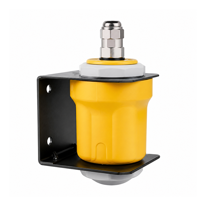
Temperature and pressure limits of the electronics
Check the process temperature rating separately from the electronics ambient limit. The complete assembly must remain within its specified conditions.
- Electronics ambient limit. Use the permitted ambient range for the actual electronics and display. Process temperature, ambient temperature, insulation and solar exposure must be checked separately.
- Process temperature at the flange. Select the approved thermal extension or remote electronics from the process and ambient temperature limits and the installation drawing.
- Pressure rating. The permitted pressure is limited by the lowest-rated applicable component, including process seal, antenna assembly, flange, gasket and temperature-dependent rating.
A process-rated antenna does not automatically protect the electronics from excessive ambient temperature. Verify the complete assembly, insulation boundary, ventilation and solar exposure.
Example: investigating echo loss in a 28 m cement silo
For this diagnostic example, assume a radar on a 28 m cement silo loses its echo for 20-40 seconds during pneumatic filling and recovers afterward. Compare the following possible mechanisms before choosing a corrective measure.
- If the loss follows the filling cycle and inspection shows a clean antenna, investigate signal attenuation and the filling-stream geometry before adding a cleaning purge.
- Candidate measures: relocate outside the filling stream, verify the solids-specific antenna and tracking settings, and add an approved purge only if deposits justify it. Evaluate 26 GHz and 80 GHz instruments by their actual process performance.
- Verify tracking during filling and settling against an independent reference. Record signal margin, lost-echo duration and recovery after each change.
Evaluate mounting position, antenna condition and signal margin together with the frequency band.
FAQ
Q1. Does 80 GHz penetrate steam better than 26 GHz?
There is no universal frequency choice for steam service. Distinguish vapor propagation effects from droplets and a wet antenna, then check pressure, temperature and the exact instrument configuration. High-pressure saturated steam may require specialized compensation; a frequency label or guided probe alone does not establish that capability.
Q2. Can I use ultrasonic in steam?
Steam, changing gas composition, temperature gradients and condensation can affect the acoustic path. Check the model's limits and test the actual conditions if ultrasound remains a candidate. Compare a rated alternative when that path cannot be made reliable, rather than applying a blanket rule to every vapor application.
Q3. How often should a purged antenna be serviced?
Base inspections on the process risk, deposit history, purge reliability and observed signal performance. Check regulators, gas quality and the specified backflow protection as well as the antenna. Define how loss of the purge utility is detected and handled; a maintenance interval alone does not establish reliable operation.
Q4. Why does the level read high in the morning and normal by noon?
Condensation is one possible explanation, not proof. Compare the selected distance, antenna condition, local reading, output signal and process state through the temperature cycle. Heating or a compatible antenna surface may help when wetting is confirmed, but neither guarantees removal of the fault without an approved design and verification.
Q5. Is a stilling well always better in steam?
No. A suitable chamber or stilling arrangement can improve geometry or surface conditions, but steam remains in the measuring path. Check hydraulic response, materials and the required vapor compensation for the rated device. Boiler-drum control and protection need an application-specific approved design, not an improvised pipe retrofit.
For this application, specify pressure, temperature, dust or mist conditions, condensation and any available purge utility. Request an application review
Related reading: Radar Level Sensor Beam Angle: What It Is and How to Size It for Your Tank | Level Measurement in Foam: When Radar Works and When It Does Not
