Chinese
 Spanish
 Russian
 Portuguese
 French
 German
 Indonesian
 Thai
 Vietnamese
 Arabic
 Italian
 Turkish
 Polish
 Japanese


A level sensor for corrosive liquids fails first at the gasket, the flange lining or the antenna seal, not at the antenna face. Each component meets a different chemical, so a single material grade is never enough. This article gives a per-component compatibility matrix and the checks required after a product changeover.
Where corrosion actually starts on the assembly
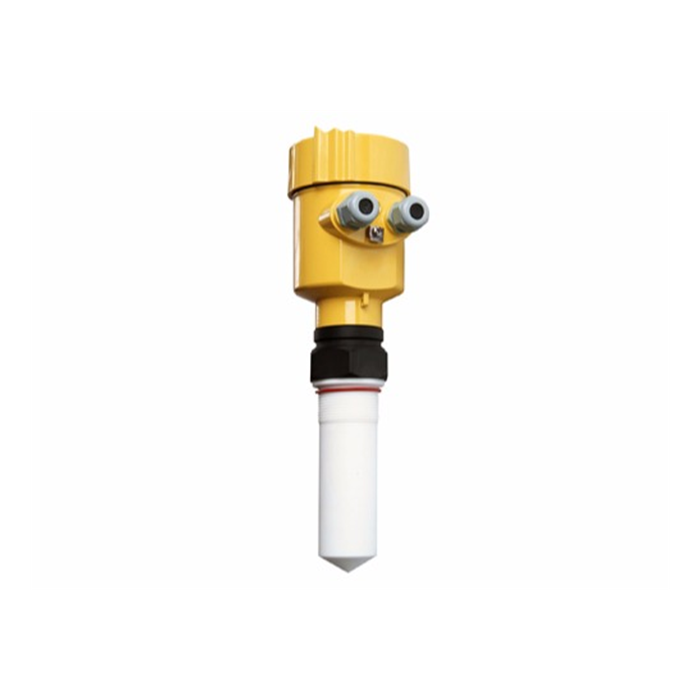
Buyers specify the antenna and stop, but the antenna is usually the last part to give way. A level sensor for corrosive liquids lives or dies at the joints: the gasket under the flange, the lining that isolates the process from the metal, and the seal where the antenna passes through the housing. A PTFE-faced antenna above a standard NBR gasket is a sensor that resists the liquid but leaks at the joint within a season.
The process side is only one chemical environment. The same assembly also meets cleaning agents, neighbouring products during changeover, and the vapour space above the liquid, which can hold condensate far more aggressive than the bulk. Treat the vapour-space material and the wetted material as two separate specifications, because a part that survives the liquid can be eaten by the condensate it never touches in the tank.
A per-component compatibility matrix
Acceptance of a level sensor for corrosive liquids should be checked component by component, not by a single "acid-proof" label. The matrix below sets a typical reference pairing of medium, temperature and the part that meets it; confirm each cell against the current chemical-resistance table and the actual site concentration before order.
| Component | 98 % H2SO4 @ 40 °C | 30 % HCl @ 25 °C | 50 % NaOH @ 60 °C | CIP caustic @ 70 °C |
|---|---|---|---|---|
| Antenna face (PTFE) | Suitable | Suitable | Suitable | Suitable |
| Gasket (PTFE) | Suitable | Suitable | Suitable | Suitable |
| Gasket (default NBR) | Not suitable | Not suitable | Not suitable | Caution |
| Flange lining (PFA) | Suitable | Suitable | Suitable | Suitable |
| Housing (316L + coat) | Suitable | Caution | Suitable | Caution |
"Caution" means the part survives but needs a verified coating and a shorter inspection interval; never accept it on a single vendor claim without the resistance table reference.
Antenna coating, lining and housing as separate checks
The three protective layers fail independently, so they must be verified independently during a level sensor for corrosive liquids acceptance. The antenna coating is read from the echo quality and a visual of the face; the lining is confirmed from the flange drawing and a batch mark, not from a photo; the housing is checked for coating continuity and a sealed cable entry that cannot let vapour reach the circuit board.
A coated housing is only as good as its cable gland. In hydrochloric acid service the vapour finds any unsealed entry and attacks the electronics from inside, a fault that shows up as intermittent drift rather than a clean failure. Specify the gland seal material to the same standard as the wetted parts, and record the batch on the acceptance sheet so a later leak can be traced to a specific supply.
A gasket that is correct on paper still weeps if the bolts do not load it. PTFE cold-flows at operating temperature, so it needs a higher seating stress than an elastomer gasket, about 20 MPa as a typical reference. On a DN80 PN16 flange with a 130 mm outside and 89 mm inside gasket diameter, the sealing area is π/4 × (0.130² − 0.089²) = 7.05 × 10⁻³ m² (illustrative calculation, assumed geometry).
The required total bolt load is the seating stress times that area: 20 × 10⁶ × 7.05 × 10⁻³ = 141 kN.
The illustrative total loads are 140 kN for four bolts at 35 kN each and 100 kN for four bolts at 25 kN each. These figures do not establish allowable bolt preload or the suitability of a flange. The flange, bolt count and grade, gasket seating stress and tightening sequence must follow the approved joint design and manufacturer instructions. Do not add bolts or increase preload from this example.
Retightening and leak testing must follow the approved procedure for the actual flange, gasket and chemical service. Do not infer permission to retighten a hot or pressurised joint from a generic time interval. Use the specified isolation, test medium, test pressure, duration and acceptance criteria; a universal 0.2 bar soap-film test is not established by this example.
CIP and cleaning compatibility
Clean-in-place cycles expose the assembly to chemicals the tank product never sees. A level sensor for corrosive liquids must tolerate the CIP agent at its operating temperature, which is often higher than the process temperature. A caustic wash at 70 °C is a different duty from storing 50 % NaOH at 60 °C, and the gasket rate that was acceptable for storage may be unacceptable for daily washing.
Write the CIP agent, concentration and temperature onto the same matrix as the product, and test the loop after the first clean, not after a year of them. Condensate formed during steam or hot caustic phases is frequently the most aggressive fluid in the system, so the vapour-space rating, not the liquid rating, should set the inspection interval for the seal.
Changeover re-verification and failure boundaries
Shared tanks that carry several products in a cycle need a re-verification each time the duty changes, because the new product may attack a part the previous one left alone. A level sensor for corrosive liquids accepted for 98 % sulfuric acid is not automatically accepted for a solvent or a chloride that the lining was never rated against. The remaining-life check below is illustrative, based on assumed site values, and is not METRAVON measured data.
Assumed site values:
- Gasket material, PTFE; initial thickness, t₀ = 3.0 mm
- Minimum allowable thickness, t_min = 1.0 mm
- Penetration rate at 98 % H2SO4, 40 °C, r = 0.02 mm/year
- Boundary temperature, 80 °C, where the rate is taken to triple
Calculation:
- Illustrative time to the assumed thickness-loss limit = (t₀ − t_min) ÷ r = (3.0 − 1.0) ÷ 0.02 = 100 years at 40 °C; this is not a gasket service-life or replacement interval.
- At 80 °C with assumed thickness-loss rate 0.06 mm/year, the same arithmetic gives 2.0 ÷ 0.06 ≈ 33 years; creep, compression and sealing failure are not modelled.
- Conclusion: the assumed thickness-loss calculation alone does not establish whether the gasket is the limiting part at 40 °C. Confirm the assumed rate and assess creep, compression, chemical compatibility and sealing condition separately.
A level sensor for corrosive liquids will fail in service when only the antenna is specified as resistant while the gasket, lining and seal are left to a default grade. A shared tank switched from an acid to a chlorinated solvent without re-checking the lining is a classic case: the new product attacks the PFA layer the acid never touched, and the first sign is a weep at the flange, not a sensor error. The method also fails if the vapour space is ignored; concentrated acid stored warm throws off condensate more corrosive than the bulk, and a housing rated only for the liquid corrodes from the top down. Specify and verify every part against the worst fluid it will meet, including CIP and the empty-tank vapour, before the unit is accepted as suitable for the duty.
Inspection interval by duty
The inspection frequency should follow the duty, not a calendar date copied from another plant. The table below sets a reference interval by how aggressively the assembly is used; tighten it where temperatures or changeover frequency are higher than the base case.
| Duty | Inspect gasket | Inspect seal | Condition |
|---|---|---|---|
| Single product, stable | 12 months | 12 months | Temperature < 50 °C |
| Multi-product shared | 6 months | 6 months | Changeover ≥ 4 / year |
| CIP-heavy service | 3 months | 6 months | Caustic > 70 °C |

Keep the chemical-resistance table reference with the inspection record; an interval set without the source rating cannot be defended in an audit.
FAQ
Q1. Why does the gasket matter more than the antenna?
The direct answer is that the gasket meets the process at a stressed, thin joint where a default grade fails long before a PTFE antenna does. A sensor with a resistant face and a standard gasket leaks at the flange within a season. Specify the gasket to the same chemical standard as the wetted face and record its batch on the acceptance sheet.
Q2. Do I need a different material for the vapour space?
The direct answer is yes, because condensate above the liquid is often more aggressive than the bulk and attacks parts the liquid never touches. A housing rated only for the stored acid can corrode from the top down during warm storage. Rate every part against the worst vapour it will meet, including CIP steam phases.
Q3. Is PTFE always safe for acids?
The direct answer is that PTFE resists most acids but is not universal, and the surrounding gasket, lining and coating must be rated too. Some solvents and strong oxidisers attack it or the adhesives that hold it. Always confirm the specific concentration and temperature against the current resistance table rather than assuming the "PTFE" label covers the whole assembly.
Q4. What must I re-check after a product changeover?
The direct answer is the lining and seal against the new product, because a shared tank may move to a fluid the previous one never challenged. Re-verify the flange lining and the antenna seal, and repeat the loop test after the first fill. Do not carry the old acceptance across a changeover without this re-check, even if the sensor model is unchanged.
Q5. How often should I inspect a corrosive-duty sensor?
The direct answer depends on the duty: 12 months for a single stable product below 50 °C, 6 months for a multi-product shared tank, and 3 months for the gasket in CIP-heavy service above 70 °C. Set the interval from the worst condition, not from a generic calendar, and keep the resistance-table reference with the record.
Q6. Can the housing be standard stainless steel?
The direct answer is only with a verified coating and a sealed cable gland, and even then treat it as "caution" for acids and CIP. Vapour entering an unsealed gland attacks the electronics from inside and shows as drift, not a clean fault. Match the gland seal to the wetted standard and record the coating batch for traceability.
SUMMARY
A level sensor for corrosive liquids is only as good as its weakest joint, so the gasket, lining and seal must each be rated against the product, the CIP agent and the vapour, where the assumed thickness-loss calculation gives 100 years but does not establish gasket service life, inspection frequency or replacement life. Compression, creep, sealing condition and chemical compatibility require separate assessment. The next step is to file the chemical-resistance table with the inspection record and re-verify the lining at every product changeover.
Talk to a METRAVON engineer about this application
If you are specifying a sensor for a corrosive or multi-product tank, send us the product list with concentrations and temperatures, plus your CIP agent. Our engineers will build a per-component material matrix and an inspection interval matched to your actual duty.