Chinese
 Spanish
 Russian
 Portuguese
 French
 German
 Indonesian
 Thai
 Vietnamese
 Arabic
 Italian
 Turkish
 Polish
 Japanese

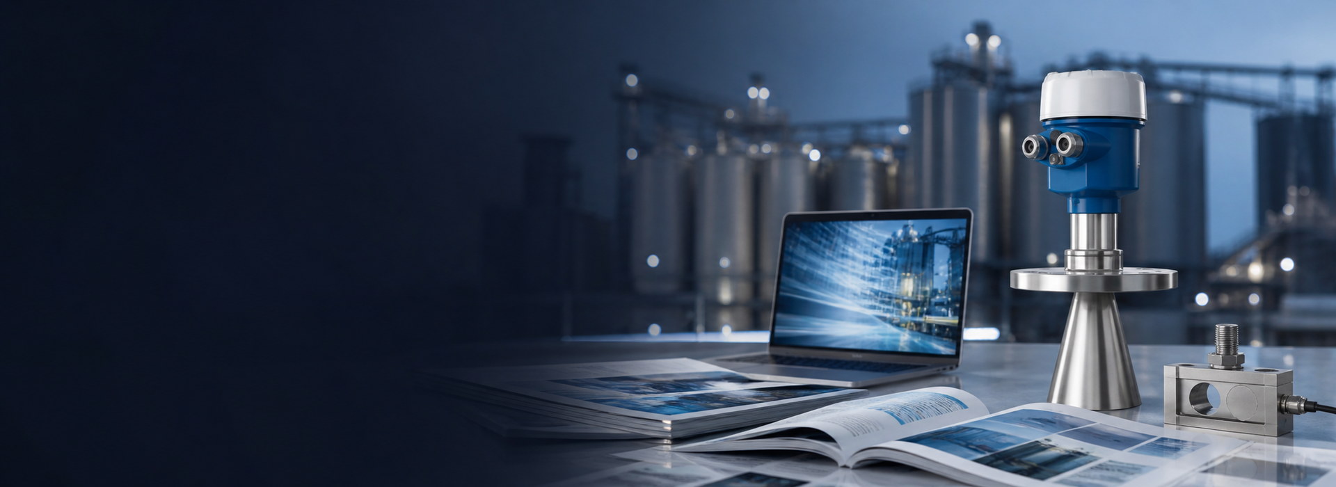
Level instrument installation acceptance is the moment a multi-device package either becomes maintainable or becomes a mystery. Good records tie each radar, ultrasonic, point switch and gateway to its mount, loop test, datum and scaling so a later technician can verify the work without the original installer. This article gives a responsibility matrix and a handover file list.
Who owns each device during construction
Level instrument installation acceptance fails most often because four device families were installed by four different crews with no single owner of the evidence. The radar transmitter, the ultrasonic transmitter, the point level switch and the telemetry gateway each need a named responsible party from mounting through sign-off. A responsibility matrix written before the first nozzle is cut prevents the classic gap where the gateway communicates but nobody confirmed the switch trip setpoint.
The matrix should name the installer, the tester and the verifier for every loop, not just every device. On a plant with 40 level loops, the loops outnumber the device types, and the loop is the unit that gets accepted. Keep the matrix as a living sheet that follows the punch-list, not a document produced only at the end when memories have faded. Where a gateway serves ten transmitters, write the gateway once as the common owner and list the ten dependent loops beneath it so the comms evidence is not duplicated or silently dropped.
Mounting checks that survive a site walk
A mount that looked correct on commissioning day can be indefensible a year later if the check was never written down. For level instrument installation acceptance, record the antenna height above the datum, the distance to the nearest tank wall, and the clearance to any internal obstacle. A radar needs at least 0.3 m from the tank wall on small vessels and 0.4 m on concrete, while an obstacle must sit more than 0.2 m from the beam path.
Record the mounting angle too: a flange that is not parallel to the liquid surface sends the beam off-vertical and the echo weakens. Photograph the installed head with a reference rule in frame, because a picture settles more arguments than a signed line on a generic form. These checks are cheap at install and impossible to recover after the scaffold comes down. For an ultrasonic head, also note the stilling tube or baffle used to calm the surface, since that detail decides whether the later dip comparison is fair.

Loop tests per instrument type
Acceptance is proven at the loop, not at the device box. The table below sets a per-type loop test and the limit that should be written on the test sheet, with the process condition under which the test is valid. Level instrument installation acceptance should collect one row per loop, dated and initialled.
| Instrument | Loop test | Acceptance limit | Valid condition |
|---|---|---|---|
| Radar level transmitter | Live level vs manual dip | ±3 mm vs dip | Still surface |
| Ultrasonic transmitter | Time-of-flight vs dip | ±5 mm vs dip | No condensation |
| Point level switch | Trip at setpoint | ±10 mm of setpoint | Raised liquid |
| Gateway | Comms + timestamp | 100 % packets, ±1 s | Network stable |

Limits are typical reference values for a clean install; confirm them against the current data sheet and the project specification before the test sheet is frozen.
Datum and scaling: the two entries most often missing
Two fields disappear from most acceptance packs: the local datum the reading is measured from, and the scaling that turns a milliampere signal into a displayed level. Level instrument installation acceptance is incomplete if a later technician must reverse-engineer either one. The scaling check below is illustrative, based on assumed site values, and is not METRAVON measured data. It is the single most useful five-minute test on a 4–20 mA loop, because it catches a wrong range before anyone trusts the display.
Assumed site values:
- Radar measuring range, 0–12.00 m
- Output, 4–20 mA into a 250 Ω receiver
- Manual dip at test, h = 4.80 m
- Acceptance tolerance on current, ±0.05 mA
Calculation:
- Expected current = 4 + (4.80 ÷ 12.00) × 16 = 4 + 6.40 = 10.40 mA
- Voltage at the receiver = 10.40 mA × 250 Ω = 2.60 V
- If the receiving DCS interprets the unchanged 10.40 mA on an incorrect 0–12.50 m scale, it displays (10.40 − 4) ÷ 16 × 12.50 = 5.00 m instead of 4.80 m.
- The displayed error is 0.20 m. Inverting the incorrect 12.50 m scale at the true 4.80 m gives an expected 10.14 mA, about 0.26 mA below the actual 10.40 mA; this is an equivalent configuration discrepancy, not a change in transmitted current.
- Boundary: the check is valid only at a still surface; repeat it after the tank has settled, not during filling.
Separating temporary trial results from permanent acceptance
A result taken during commissioning is not the same grade of evidence as a permanent acceptance reading, and level instrument installation acceptance must keep the two tiers apart. A radar echo captured while the tank was being flushed, or a point switch tripped from a bench simulator rather than from the real rising liquid, proves the hardware worked once under special conditions. It does not prove the installed duty is correct.
This two-tier filing method will fail when a single temporary trial, taken during foam, filling or an empty tank, is signed as permanent acceptance. An ultrasonic loop accepted from one dry check will also fail the day the vapour space condenses and the time-of-flight shifts. Tag every trial "temporary", store it in a separate section, and require a permanent, condition-correct reading before the loop is closed on the punch-list.

The handover file list
The acceptance pack should hand over as a set, not as a pile of loose PDFs. The list below is the minimum a plant should receive for level instrument installation acceptance; it covers all four device families and the evidence a future shutdown will need. Bundle the files against the loop register, not against the device model. A technician sent to loop 23 then finds every document for loop 23 in one place rather than hunting across folders named by manufacturer.
Size the pack before the final commissioning week, because the volume surprises most teams. Forty loops at five documents each is 200 records; scanned at 300 dpi into PDF/A and indexed at two minutes per record, the work is under 7 h spread across the programme and it routinely stretches into days if it is left to the end. The index must key on loop number with the device tag as a secondary field, or the records exist but cannot be found.
Test that retrieval before handover. Ask a technician who did not build the loop to produce its mounting datasheet, loop sheet, datum sketch, scaling record and certificate. Five lookups spread across four vendor folders cost 15–20 min at 3–4 min each; the same five files behind a loop-keyed index take under 60 s. A result above 5 min points at the index, not at the technician, and it is cheaper to fix that week than after the commissioning team has demobilised.
| Document | Owner | Retention rule |
|---|---|---|
| Mounting datasheet | Installer | Life of plant |
| Per-loop test sheet | Tester | Life of plant |
| Datum sketch | Tester | Life of plant |
| Scaling record | Verifier | Life of plant |
| Calibration certificate | Vendor | Until next cal |
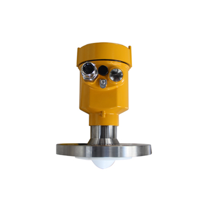
Keep the calibration certificate with its serial number matched to the physical tag; a certificate that cannot be tied to a device is not evidence during an audit.
Two copies on separate media is the working minimum for a life-of-plant file, and the plant's own retention rule governs the rest. The calibration certificate can be released when the next calibration supersedes it, but the loop sheet, datum sketch and scaling record must survive every modification, because each describes the installation as built, not as designed.
FAQ
Q1. What is the difference between a loop test and a device test?
The direct answer is that a device test proves the box works, while a loop test proves the signal reaches the controller correctly. Acceptance should be at the loop: radar live level versus a manual dip, switch trip at the setpoint, gateway packets arriving with the right timestamp. Accept only loops, because the device alone does not show a broken cable or a wrong scale.
Q2. How far from the tank wall must a radar be mounted?
The direct answer is at least 0.3 m on a small metal vessel and 0.4 m on a concrete tank, measured from the antenna axis to the wall. Closer than that and the beam reflects off the wall, giving a stable false reading. Also keep any internal obstacle more than 0.2 m from the beam path, and photograph the clearance at install.
Q3. Why does the datum sketch matter years later?
The direct answer is that without it, nobody can tell what height the reading is measured from, so a replacement technician cannot verify the level. The sketch records the antenna height above a surveyable reference and the zero of the scale. File it with the loop sheet, because the sensor firmware alone does not preserve the physical offset.
Q4. Can a simulator trip replace raising the real liquid?
The direct answer is no, not for permanent acceptance. A bench simulator proves the switch electronics respond, but not that the installed setpoint matches the real rising surface. Raise the actual liquid past the setpoint during the loop test, and record the level at which it tripped within ±10 mm of the setpoint.
Q5. Why keep temporary trial results separate?
The direct answer is that a trial taken during flushing, foam or filling proves only a special condition, not the installed duty. Mixing it with permanent readings hides which evidence is condition-correct. Tag trials "temporary" in a separate section and require a still-surface reading before the loop is closed on the punch-list.
Q6. What scaling error does a wrong range cause?
A wrong receiving range changes the displayed level. With a transmitter configured for 0–12 m, a true 4.80 m level gives 10.40 mA. A DCS incorrectly scaled to 0–12.5 m interprets that same current as 5.00 m. The inverse calculation for 4.80 m on the wrong scale gives 10.14 mA, about 0.26 mA lower, but receiver scaling does not alter the physical loop current. Check the current and both configured scales against an independent level reference.
SUMMARY
Level instrument installation acceptance is durable only when each of the four device families is tied to a mount record, a per-loop test, a datum sketch and a verified scaling, where a 4.80 m dip on a 0–12 m radar must read 10.40 mA within ±0.05 mA. The next step is to file the handover set with serial numbers matched to certificates so a future shutdown can trust the evidence.
Talk to a METRAVON engineer about this application
If you are coordinating a multi-instrument level package, send us the loop count by device type and the project acceptance specification. Our engineers will propose a responsibility matrix and a test-sheet format that keeps temporary and permanent results in separate, auditable tiers.