


 Chinese
 Spanish
 Russian
 Portuguese
 French
 German
 Indonesian
 Thai
Thai Vietnamese
 Arabic
 Italian
 Turkish
 Polish
 Japanese

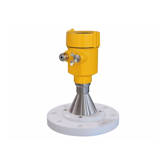
What Should You Consider When Purchasing an 80GHz Radar Level Meter?
An 80GHz radar level meter, generally referring to a 76–81GHz FMCW radar level meter, features a narrow beam angle of approximately 3° or less, a small dead zone commonly around 8cm, a high signal-to-noise ratio, and strong resistance to steam and dust. It is suitable for small tanks, storage tanks containing internal obstacles, and complex process conditions. When purchasing one, the medium, operating conditions, installation conditions, and output requirements must be carefully matched.
First, confirm the dielectric constant of the medium. A liquid with a dielectric constant of ≥2 normally provides good signal reflection. If the dielectric constant is below this value, it is necessary to evaluate whether a guided wave radar should be used instead or whether signal reflection enhancement measures should be adopted. The process temperature and pressure must fall within the rated range of the instrument. Common process temperature ranges are from -40℃ to 200℃ or higher, while common pressure ranges are from -0.1 to 2MPa; the actual values depend on the specific model. For corrosive media, a PTFE/PFA lens or corrosion-resistant antenna should be selected. For media prone to adhesion or crystallization, a non-contact model should be prioritized, together with a purging or cleaning design.
Installation conditions determine whether the instrument can operate successfully. An 80GHz model is preferred for small-diameter nozzles or confined spaces because its antenna is smaller and its beam is more focused, allowing it to avoid agitators, heating coils, ladders, and other internal structures. The measuring range must include an adequate allowance, and the highest material level must never enter the measuring dead zone. The output signal, such as 4–20mA, HART, or RS485/Modbus, and the power supply method, with two-wire loop power being commonly used, must be compatible with the existing DCS or PLC. Explosion-proof requirements, the protection rating, with IP67 being common, and relevant certifications should be selected according to the hazardous area classification at the site.
Purchasing recommendation: provide the supplier with a complete operating-condition datasheet, including the medium name and dielectric constant, temperature and pressure curves, tank dimensions and internal structure drawings, and mounting flange or thread specifications. Request examples of echo curves and an explanation of the instrument’s false-echo suppression capability. The METRAVON 80GHz series supports lens antennas, multiple process connections, and local push-button displays, making parameter configuration and subsequent maintenance more convenient. It is suitable for engineering-scale procurement and long-term stable operation.
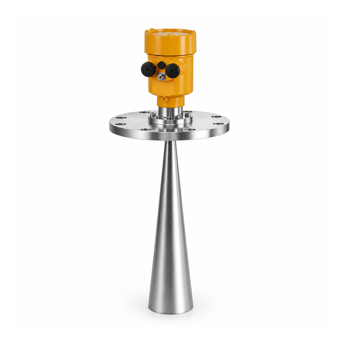
What Are the Outstanding Advantages of Guided Wave Radar Level Meters?
Guided wave radar, or GWR, guides microwave signals along a probe rod or cable, concentrating the signal energy and reducing attenuation. It complements non-contact radar technology. Its outstanding engineering advantages include:
It has a smaller overall size and requires less installation space, making it particularly suitable for small tanks and restricted nozzles. It provides more reliable measurement for media with low dielectric constants because the signal travels along the guided probe and the reflected signal energy is relatively strong, making it one of the better choices for low-dielectric-constant applications. Models equipped with a push-button display allow parameters to be configured directly on site, reducing dependence on host-computer software. The measuring dead zone is smaller, enabling good performance even in tanks with short measuring ranges.
Concentrated signal energy provides stronger resistance to interference and greater stability. Dynamic signals and narrower pulses help improve accuracy and repeatability. The instrument offers sensitive measurement, fast response, easy installation, a robust structure, and routine maintenance-free operation. In general, it is not significantly affected by complex conditions such as temperature, pressure, water vapor, foam, and dust. A microprocessor and specialized echo-processing technology allow it to adapt to various operating conditions. Its low transmission power allows installation in metal or non-metal containers without harming people or the environment. Two-wire loop-powered technology enables the power supply and output signal to share the same two-core cable, reducing wiring costs.
Application guidance: when a tank contains an agitator, the liquid surface fluctuates significantly, the vessel is small, or the medium has a low dielectric constant, guided wave radar is often more stable than non-contact radar. It also has greater advantages when interface measurement, such as oil-water interface measurement, is required. Because it is a contact measurement method, the effects of medium adhesion and corrosion on the probe must be considered, and its measuring range is generally shorter than that of a non-contact 80GHz radar. The METRAVON guided wave series offers various probe options, including rod and cable types, for small tanks and complex process applications, facilitating accurate engineering matching.
Where Should the Top Material Level or High-Level Point of a Radar Level Meter Be Set?
The core principle of high-level setting is that the highest material level must not enter the measuring dead zone. The measuring reference plane of the instrument is normally the threaded connection surface or flange sealing surface. In actual use, the distance between the highest material level and the antenna or reference point must be greater than the instrument’s dead-zone value, with an additional safety allowance.
During installation and parameter configuration, first use the tank drawing to confirm the distance from the sealing surface to the highest permitted liquid level. Then correctly enter the empty-tank distance, or E value, and the full-tank distance in the instrument menu. If the highest liquid level approaches the dead zone, measurement distortion, a false full-tank signal, or signal loss may occur. Domed-roof tanks and tanks with curved roofs can easily produce multiple reflections. The installation position should therefore be offset from the center and placed at a suitable position closer to the outer side. The radar beam must not intersect the filling stream.
Engineering recommendation: before commissioning, verify the measurement using a known liquid level or an empty-tank condition, and enable the false-echo learning function. METRAVON instruments support dead-zone and measuring-range configuration through local push buttons or software, allowing high-level protection parameters to be configured quickly according to the actual tank dimensions.
What Are the Common Faults of Radar Level Meters?
When the antenna condition and installation are normal and there are no obvious obstacles inside the tank, faults are generally concentrated in the instrument itself or in electrical parameters. Common problems and recommended troubleshooting directions are as follows:
Software or hardware failure: upgrade the software, replace the instrument, or return it to the factory for repair.
Current signal above 22mA or at 0mA: this is usually caused by damaged electronic components. Replace the affected components promptly or return the instrument for repair.
Unstable 4–20mA signal: this is generally caused by material-level fluctuations. Adjust the integration time, or damping, through the module or software such as PACTware.
Loss of the 4–20mA signal: check the power-supply wiring, whether power is connected, whether the supply voltage is too low, or whether the load resistance is too high. Verify the wiring and power-supply reliability according to the wiring diagram, inspect the cable and fuse, and correct any mismatch between the voltage and load.
Other common conditions include signal loss caused by antenna fouling, strong false echoes generated by fixed obstacles, and signal fluctuations caused by electromagnetic interference. The recommended troubleshooting sequence is to first confirm the power supply and wiring, then inspect the echo curve, and finally adjust the parameters or clean the antenna. Do not open an explosion-proof enclosure while it is energized. METRAVON products support echo-curve display and false-echo suppression, facilitating rapid on-site diagnosis.
How Should a Radar Water Level Meter Be Installed?
The mounting bracket and sensor of a radar water level meter used in rivers, reservoirs, and similar applications must ensure vertical alignment and long-term protection. A typical installation uses two sections of DN100 galvanized steel pipe for the vertical post. The overlapping section is secured using two bolts arranged vertically and crosswise. The pipe wall thickness is approximately 3.5mm. A flange is welded to the bottom, and a 40 × 40mm cable-routing hole is made approximately 170mm above the bottom end. The support arm is fabricated by welding DN40 and DN50 galvanized steel pipes together, with reserved cable-routing holes. The sensor is installed at the end of the horizontal arm, with the sensing end aligned vertically at 90° to the water surface. All wiring is concealed inside the horizontal arm. Connections are wrapped with waterproof tape, and all gaps are sealed to prevent the ingress of water and insects.
A water-quality instrument probe can be extended to the middle or lower part of the river channel using galvanized pipe. Depending on actual site conditions, it may be secured by direct burial, pipe clamps, a right-angle inspection chamber, or a concrete post. The structural material should be Q235 steel with hot-dip galvanizing followed by powder coating. A lightning rod made from φ10mm round steel, approximately 500mm long and sharpened at the top, should be welded to the upper section while preventing rainwater from entering. A cable outlet should be provided at the integrated equipment-enclosure position on the main pole. The equipment-enclosure bracket should be welded from flat steel with a thickness of 3mm, ensuring a load-bearing capacity of at least 50kg. A cable-routing opening approximately 10cm long and φ35mm in diameter should be welded beneath the bracket.
After installation, confirm that the sensor is unobstructed and properly vertical, and then verify the zero point and measuring range. METRAVON mounting brackets and sensor solutions can be customized according to actual river conditions to meet the requirements of long-term and stable outdoor monitoring.
How Should a Radar Level Meter Be Commissioned?
There are three main commissioning methods:
Measurement and configuration through host-computer software, which is supported by most sensors.
Parameter configuration through the instrument’s built-in display and adjustment module.
Commissioning through a handheld programmer.
Basic procedure: after completing installation, switch on the power and confirm that the display operates normally. Enter basic parameters such as the empty-tank distance, full-tank distance, and medium type. Observe the echo curve and perform false-echo learning. Set the damping time to suppress fluctuations. Verify that the 4–20mA output corresponds correctly to the actual liquid level. Under complex operating conditions, advanced functions such as agitator mode or foam-penetration mode may be enabled. After commissioning is complete, lock the parameters and record the configuration data.
METRAVON instruments support multiple commissioning methods, including local operation through a push-button display, software configuration, and Bluetooth on selected models, reducing on-site workload.
FAQ
Q1: How should an 80GHz radar level meter and a 26GHz radar level meter be selected?
A: An 80GHz model, with its narrow beam and small dead zone, should be prioritized for tanks with internal obstacles, small nozzles, high-accuracy requirements, or heavy steam or dust. A 26GHz model can be considered for simple liquid applications or cost-sensitive projects. The final choice must also take the dielectric constant and measuring range into account.
Q2: Which low-dielectric-constant media are suitable for guided wave radar?
A: Guided wave radar is generally more stable for media with relatively low dielectric constants that are still ≥ approximately 1.4, such as certain light oils and solvents. Media with extremely low dielectric constants require actual testing or the addition of a bottom reflector plate.
Q3: What happens if the high material level enters the dead zone?
A: Measurement distortion, a false full-tank indication, or signal loss may occur. The highest material level must remain outside the dead zone, with an adequate allowance.
Q4: What should be checked first when the 4–20mA signal is lost?
A: Check the supply voltage, wiring correctness, fuse, and whether the load resistance is too high. After confirming that the power supply is reliable, inspect the instrument’s electronic components.
Q5: Must a water level meter be installed vertically?
A: Yes. The sensing end must be aligned at 90° to the water surface. Tilting can cause distance-measurement errors. The bracket must provide sufficient rigidity and vibration resistance.
Q6: Must the tank be empty during commissioning?
A: An empty tank or a known liquid-level condition is most suitable for accurately setting the zero point and performing false-echo learning. If the tank is not empty, a known reference point can be used for assistance.
Q7: Does foam affect measurement?
A: Thick foam may cause interference. An 80GHz radar has relatively strong penetration capability, while guided wave radar also provides good resistance to foam interference. The appropriate algorithm can be enabled, or the installation position can be adjusted.
Q8: What are the advantages of a two-wire system?
A: The power supply and signal share the same two-core cable, saving wiring costs and space and making it suitable for most process-control loops.
Q9: What information must be provided when purchasing?
A: Provide the medium name and dielectric constant, temperature and pressure, tank dimensions and internal structure, mounting-interface specifications, output requirements, and explosion-proof requirements. This information enables accurate model selection.
Q10: Which commissioning methods do METRAVON products support?
A: Local push-button displays, host-computer software, handheld programmers, and Bluetooth on selected models are supported to meet different on-site requirements.
Conclusion
80GHz radar level meters and guided wave radar level meters each have their own focus in engineering applications. The former features a narrow beam, a small dead zone, and strong resistance to interference, making it suitable for complex non-contact measurements. The latter offers concentrated signals, adaptability to low-dielectric-constant media, and advantages in confined spaces. During procurement, the instrument must be matched to the medium and operating conditions. The high material level must remain strictly outside the dead zone, installation must ensure vertical alignment and obstacle avoidance, false-echo suppression and parameter locking must be completed during commissioning, and troubleshooting should follow the sequence of power supply → wiring → echo → parameters. Standardized implementation can significantly improve measurement reliability and overall system availability.
METRAVON specializes in engineering-grade radar level measurement solutions. Its product range covers 80GHz non-contact radar and guided wave radar series and supports various antennas, process connections, and output protocols. METRAVON can provide matched product selection and technical support for chemical processing, water treatment, storage tanks, and water level monitoring. If you require specific model datasheets, installation drawings, or operating-condition matching recommendations, please provide detailed process conditions with your inquiry. We will respond promptly and assist you in completing reliable product selection and delivery.
