


 Chinese
 Spanish
 Russian
 Portuguese
 French
 German
 Indonesian
 Thai
Thai Vietnamese
 Arabic
 Italian
 Turkish
 Polish
 Japanese

Engineering Summary
A guided wave radar level transmitter sends high-frequency electromagnetic pulses along a rod, cable, or coaxial probe. When the pulse reaches a surface or interface where dielectric properties change, part of the signal is reflected back. The instrument uses the return time to calculate level or interface position. Guided wave radar is valuable for small vessels, narrow spaces, agitated service, some low-dielectric media, and interface measurement, but probe length, buildup, mechanical loading, and material compatibility must be considered.
Table of Contents
What Is a Guided Wave Radar Level Transmitter?
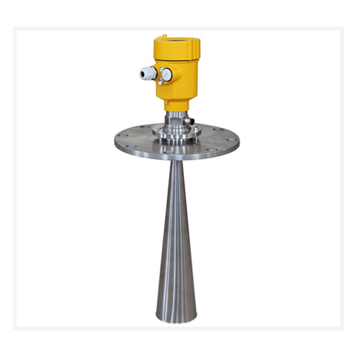
A guided wave radar level transmitter uses a metallic rod, cable, or coaxial structure to guide electromagnetic pulses toward the process medium.
Free-space radar propagates through the vapor space. Guided wave radar propagates along a probe.
When the guided signal reaches a liquid surface, bulk solids surface, or interface where dielectric properties change, part of the energy is reflected back along the same path.
How Does Guided Wave Radar Work?
High-Frequency Pulse → Probe / Cable Propagation → Product Surface → Reflected Echo → Return Along Probe → Signal Processing → Distance → Level
For time-of-flight guided wave radar:
d = c × t / 2
If E is the empty reference distance:
H = E − d
Depending on the model, the instrument can output level, distance, percentage, and sometimes interface position.
What Is TDR?
TDR stands for Time Domain Reflectometry . A fast electromagnetic pulse travels along a conductor and reflects where impedance or dielectric conditions change. The instrument measures return time and echo behavior to locate the reflection point.
Rod, Cable, and Coaxial Probe Types
Rod Probe
A rigid metallic rod is mechanically stable and suitable for many small and medium tanks. Installation requires enough vertical space for the full rod length.
Cable Probe
A flexible cable is useful for taller tanks and is easier to transport. Strong agitation can move the cable, and sticky products can build up on it. Depending on the application, bottom anchoring or a weight may be required.
Coaxial Probe
A coaxial design confines the electromagnetic field more strongly and can perform well in some low-dielectric or small-vessel applications. However, the narrow internal spacing makes it more sensitive to viscous buildup, crystallization, and high-solids slurry.
Why Does Dielectric Constant Matter?
Guided wave radar concentrates energy along the probe, but reflection strength still depends on the dielectric change at the product surface.
Compared with free-space radar, guided propagation can improve signal stability in some low-dielectric media. However, it is not correct to state that guided wave radar is completely independent of dielectric constant.
Guided Wave Radar vs. Free-Space Radar
| Item | Guided Wave Radar | Free-Space Radar |
|---|---|---|
| Signal Path | Along rod or cable | Through vapor space |
| Process Contact | Probe normally contacts the medium | Normally non-contact |
| Probe Length | Must match the application | No long probe required |
| Small Vessels | Often advantageous | Beam interaction with walls must be considered |
| Narrow Spaces | Good candidate | High-frequency narrow-beam radar can also work well |
| Agitated Surface | Can be stable if the probe is properly supported | Depends on beam, filtering, and echo tracking |
| Sticky Product | Probe buildup can directly affect measurement | Antenna is normally above the product |
| Very Long Range | Limited by probe length and mechanics | Often more suitable |
| Maintenance | Inspect rod/cable | Inspect antenna and mounting area |
Guided Wave Radar vs. 80 GHz Radar
When Guided Wave Radar Is Often Worth Considering
Small-diameter tanks
Moderate measurement range
Applications where guided energy is beneficial
Some low-dielectric liquids
Interface measurement
Agitated surfaces where the probe can be mechanically stabilized
When 80 GHz Free-Space Radar Is Often Worth Considering
Completely non-contact measurement is preferred
Sticky or coating media
A long probe is impractical
Tall tanks
Small process connections
Complex internals requiring a narrow beam
Bulk solids silos
80 GHz radar is not simply “more advanced” than guided wave radar. The two technologies solve different mechanical and process problems.
How to Integrate Guided Wave Radar with PLC, DCS, or RTU
4–20 mA
Guided Wave Radar → 4–20 mA → PLC AI / DCS
4–20 mA/HART
Guided Wave Radar → 4–20 mA/HART → PLC / DCS / HART System
HART can support device configuration, range setup, diagnostics, and status information in addition to the primary analog level signal.
RS485 Modbus RTU
Some models may support digital communication. Confirm the specific product configuration.
Guided Wave Radar → RS485 Modbus RTU → RTU / PLC / Industrial Gateway
Radar → RS485 → Gateway → 4G / Ethernet → MQTT / HTTP → SCADA / IoT
Guided Wave Radar Installation
1. Avoid Direct Filling Impact
The filling stream can cause probe movement, mechanical stress, buildup, and abnormal echoes.
2. Keep the Probe Away from Tank Walls and Internals
Long-term contact with walls, supports, coils, or other metal internals can create additional reflections and mechanical wear.
3. Consider Bottom Anchoring for Long Cable Probes
In strong agitation or flow, a long cable may require anchoring. The design must account for tension, thermal expansion, mechanical load, and maintenance access.
4. Match Probe Length to the Vessel
Before ordering, confirm tank height, process connection-to-bottom distance, lowest measurement position, bottom clearance, and whether anchoring is required.
5. Protect Outdoor Cable Entries
Check cable glands, housing seals, drip loops, shield grounding, and enclosure rating.
Commissioning and Configuration
Common commissioning methods include local LCD/keys, HART handheld communicator, PC software, or an asset management system.
At minimum, confirm empty reference distance, full calibration, probe length, medium type, engineering unit, 4 mA and 20 mA scaling, damping, application mode, and any end-of-probe or false-echo settings.
How to Read the Echo Curve
Typical echo features may include the launch pulse, process connection reflection, true product surface echo, interface echo, probe-end echo, and reflections from fixed structures.
Do not assume that the highest peak is always the correct level. Compare the echo curve with the known level, empty reference distance, probe length, fixed interference locations, and tracking status.
Common Problems and Troubleshooting
| Symptom | Common Causes | What to Check |
|---|---|---|
| Level jumps | Buildup, structural echo, probe movement, parameter issue | Echo curve and probe condition |
| High level not detected | Upper blocking distance or process connection interference | Zero point and blocking distance |
| Low-level error | Product echo confused with end-of-probe echo | Probe length and end-of-probe settings |
| Instability during agitation | Rod/cable movement or rapidly changing surface | Mechanical support and damping |
| Long-term drift | Probe buildup or crystallization | Probe cleanliness |
| 4–20 mA works, HART fails | Loop impedance or compatibility issue | HART loop design |
| RS485 no response | A/B, address, baud rate, register configuration | Modbus RTU parameters |
Why Is Probe Buildup Important?
Because the rod or cable directly enters the process area, sticky liquids, crystallizing products, slurry, resin, and high-solids media can create additional reflections along the probe.
For severe buildup service, free-space 80 GHz radar may be more attractive.
Can Guided Wave Radar Measure an Interface?
Some guided wave radar models can measure both total level and an interface between two immiscible liquids. Stable interface measurement depends on the dielectric properties of the upper and lower phases, emulsion layer, foam, probe type, and the specific instrument algorithm.
Typical METRAVON Industrial Applications
1. Chemical Storage Tanks
Guided Wave Radar → 4–20 mA/HART → PLC / DCS
2. Small Reactors and Agitated Tanks
Guided propagation can reduce the influence of narrow vessel geometry where free-space beams interact strongly with walls.
3. Oil/Water or Liquid/Liquid Interface Measurement
Use an interface-capable model and confirm dielectric contrast and emulsion conditions.
4. Small Industrial Tanks
Guided wave radar can be useful where vessel diameter is small and free-space beam clearance is limited.
5. PLC / DCS / RTU Integration
Guided Wave Radar → 4–20 mA / HART / RS485 → PLC / DCS / RTU
Guided Wave Radar Selection Checklist
| Item | What to Confirm |
|---|---|
| Medium | Product name, liquid/slurry/solid |
| Dielectric Behavior | Used to assess echo strength and probe type |
| Tank Height | Determines probe or cable length |
| Tank Diameter | Determines installation space |
| Process Temperature | Normal and maximum |
| Process Pressure | Normal and maximum |
| Viscosity | Used to assess buildup risk |
| Agitation | Determines mechanical support requirements |
| Internals | Coils, agitators, supports, etc. |
| Process Connection | Thread, flange, size |
| Probe Type | Rod, cable, coaxial, etc. |
| Output | 4–20 mA, HART, RS485 |
| System | PLC, DCS, RTU, industrial gateway |
| Interface Measurement | Whether total level and interface are both required |
FAQ
Q1: Is guided wave radar a non-contact radar?
Not in the same sense as free-space radar. The rod or cable normally contacts the process medium.
Q2: Is guided wave radar always more stable than free-space radar?
No. It can be advantageous in small vessels, some low-dielectric media, or mechanically stable agitated service. Free-space radar can be better where buildup is severe or very long range is required.
Q3: Can guided wave radar measure low-dielectric liquids?
Often yes, but dielectric constant still affects echo strength. It should not be treated as completely independent of dielectric properties.
Q4: Does a cable probe always require bottom anchoring?
No. Anchoring may be considered for long probes or strong agitation according to the product design.
Q5: Can the probe be cut to length in the field?
Not always. Some models allow controlled shortening with probe-length reconfiguration; others do not. Follow the specific product instructions.
Q6: Is guided wave radar suitable for viscous products?
It can be, but severe buildup on the probe can create additional echoes. Free-space radar may be preferable for strongly coating media.
Q7: Can guided wave radar measure an oil/water interface?
Some models can, provided the dielectric conditions and emulsion layer are suitable.
Q8: Why can low-level measurement become unstable?
The true product echo may approach the end-of-probe echo. Check probe length, end-of-probe behavior, and lower blocking settings.
Q9: Which is better for a small tank, guided wave radar or 80 GHz radar?
Both can work well. Guided wave radar confines the signal to the probe, while 80 GHz radar uses a narrow free-space beam. The best choice depends on buildup, installation space, and process connection.
Q10: Can guided wave radar connect directly to a PLC?
Yes, depending on whether the specific model provides 4–20 mA, HART, or RS485 Modbus RTU.
Conclusion
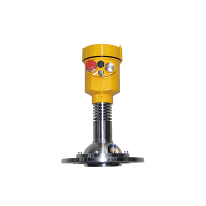
Guided wave radar directs electromagnetic energy along a rod or cable and calculates level from the reflected echo. It is especially useful in small vessels, narrow spaces, some low-dielectric media, and interface applications, but probe length, buildup, mechanical loading, temperature, pressure, and interface requirements must be considered.
METRAVON Guided Wave Radar and Level Measurement Selection
For project evaluation, provide medium name, dielectric behavior, maximum and minimum level, tank height and diameter, temperature, pressure, viscosity, crystallization or buildup conditions, agitation, process connection, interface measurement requirements, output interface, host system, and site photos or vessel drawings.
