


 Chinese
 Spanish
 Russian
 Portuguese
 French
 German
 Indonesian
 Thai
 Vietnamese
 Arabic
 Italian
 Turkish
 Polish
 Japanese



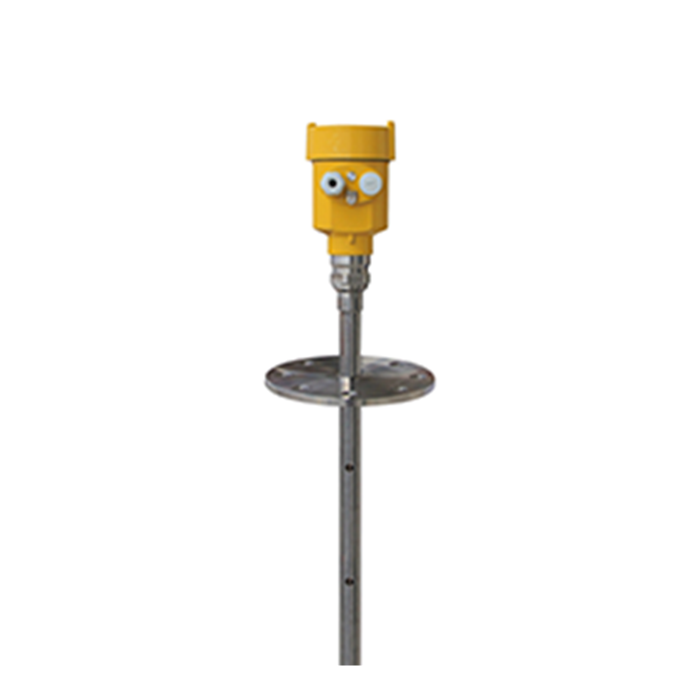
METRAVON MV-RD704 is a coaxial guided wave radar level meter for liquids. A centre conductor and surrounding tube guide the measurement pulse, making this structure useful to assess for compact vessels and low-dielectric liquids. The tube is part of the probe, not merely a protective cover: liquid must enter and leave it freely for the measurement to represent the vessel level.
Will the liquid remain free-flowing inside the probe?
Start with viscosity, solids content and the possibility of crystallisation or deposits. A clean liquid can behave very differently from the same product after cooling or an extended shutdown. Material that blocks the openings or accumulates between the conductors can interfere with level tracking. Plan access for inspection and cleaning before selecting a long, rigid assembly.
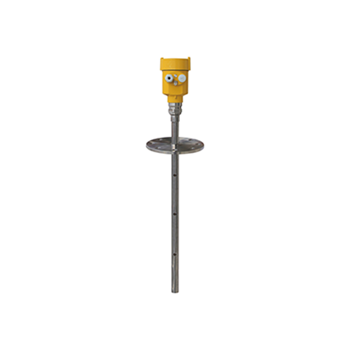
Dimensions for a coaxial guided wave radar level meter
| Dimension or option | Selection check |
|---|---|
| Listed measuring range | 0.3-6 m; identify the actual reference plane and probe-end exclusions. |
| Coaxial tube options | 25 mm / 40 mm |
| Wetted metal | 304 / 316L stainless steel |
| Connection envelope | Check nozzle bore, thread or flange details and the complete insertion path. |
| Withdrawal clearance | Allow room to remove the ordered length without bending the probe. |
| Top measuring limit | Request the configured dead zone before locating a near-full alarm. |
A compact vessel does not automatically require a short measuring span, and a small process connection does not prove that every probe option will pass through it. Confirm the selected tube diameter on the assembly drawing. If removal space is unavailable, compare the mechanical requirements of a single-cable MV-RD701 rather than bending a rigid probe to fit.
Set the operating envelope before selecting the seal
Submit pressure and temperature together, including vacuum, cleaning and startup conditions. Do not combine the highest temperature option with the highest pressure option without a rating for that complete assembly. State the fluid composition so the probe metal, seal and process connection can be assessed as wetted parts.
The two-wire electronics use 24 VDC with 4-20 mA/HART. Order RS485/Modbus as a specified electronics configuration if a digital connection is needed. For analogue commissioning, compare known liquid levels with both the local indication and the PLC's scaled reading. Check the receiving value at low and high operating levels, not only at the midpoint.
Questions for small vessels and interface service
Q1. Can this probe measure all the way to the connection?
Do not assume a zero upper dead zone for a standard unit. A near-connection measuring requirement needs a configuration-specific drawing and test condition. Keep a high-level operating point within the confirmed usable span, and assess any independent overfill protection separately.
Q2. Does a coaxial probe remove the need to assess an oil-water interface?
No. Identify both liquids, their dielectric behaviour, layer thickness and emulsification. The probe structure helps guide the pulse but does not guarantee a distinct interface return. Define whether the instrument must report surface level or interface level and verify that duty during acceptance.
Q3. What should be checked if the reading lags after filling?
First compare the local indication with the control-system value to separate signal scaling from measurement behaviour. After safe isolation, inspect the liquid entry openings and the probe for deposits. Also review damping settings; do not compensate for a blocked flow path by changing the calibration.
Attach the vessel section, nozzle dimensions, liquid properties, level span and maintenance clearance to your MV-RD704 quotation request. Specify the required output and operating conditions so the offer identifies a usable assembly rather than only a model number.
