


 Chinese
 Spanish
 Russian
 Portuguese
 French
 German
 Indonesian
 Thai
 Vietnamese
 Arabic
 Italian
 Turkish
 Polish
 Japanese



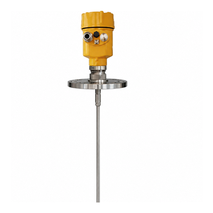
METRAVON MV-RD701 is a guided wave radar level meter with a single rod or cable probe for liquids and selected bulk solids. The probe extends into the vessel and carries the measurement pulse to the material surface. Choose it when a continuous contact probe can be installed clear of moving equipment, inlet flow and obstructions; it is not a non-contact radar.
Rod or cable: choosing a guided wave radar level meter
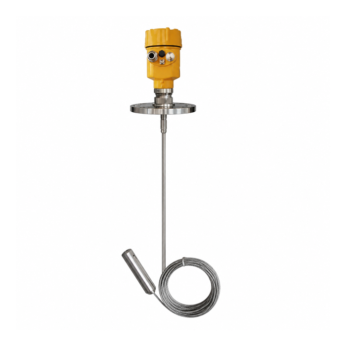
A rigid rod needs enough headroom for insertion and removal. A flexible cable is easier to handle on a tall vessel, but material movement can pull it sideways or place tension on the mounting. The 30 m maximum cable length does not apply to the rod, which is listed up to 6 m. Neither length is a promise that the complete probe, including its end regions, can measure level.
| Selection item | What to specify |
|---|---|
| Probe form | Single rod or cable; include the insertion length and removal space. |
| Maximum probe length | Cable: 30 m; rod: 6 m |
| Wetted metal options | 304 / 316L stainless steel |
| Connection | Thread or flange matched to the nozzle dimensions and pressure class. |
| Two-wire electronics | 24 VDC, 4-20 mA/HART |
| Other communication | Specify RS485/Modbus electronics and its separate power and terminal arrangement. |
Leave a clear path for the probe
Provide a section drawing showing the nozzle, internal pipes, ladders, heating coils and agitators. A cable that hangs clear when the vessel is empty may move into an obstruction during filling. Do not place the probe in the incoming material stream. For a powder silo, include bulk density, discharge behaviour and any proposed bottom attachment so the probe load and support can be reviewed before fabrication.
Record the highest required level and lowest useful level relative to the instrument reference plane. Keep both within the approved measuring span, outside the upper and lower dead zones. If an overfill alarm must operate close to the connection, check that position explicitly instead of equating the tank height with the sensor span.
When another probe is more appropriate
Bare stainless steel is not a substitute for a corrosion assessment. For an acid or alkali tank, compare the coated MV-RD702 after identifying the chemical and temperature. A compact clean-liquid vessel may instead justify the MV-RD704 coaxial probe. Sticky deposits or strong mechanical loading can make any immersed probe unsuitable; describe these conditions before choosing the measuring principle.
Commissioning and quotation details
For an analogue connection to a PLC, agree which level corresponds to 4 mA and which to 20 mA, then compare the local reading, loop current and PLC display at known levels. For RS485, request the register map and verify address, baud rate, units and lost-communication handling. Do not assume HART and RS485 share the same terminals.
Send the medium, vessel drawing, operating pressure and temperature, probe length, wetted material and required output with your MV-RD701 enquiry. Include shutdown or cleaning conditions if they exceed normal operation. The quoted probe, seal, connection and housing must be rated together; a family temperature or pressure maximum is not sufficient for approval.
Questions before installation
Q1. Can the cable simply be shortened on site?
Do not cut it without the procedure for that probe assembly. Shortening can change the end attachment and the configured probe length. Obtain the permitted adjustment method, then recheck the measuring limits and calibration before putting the loop into service.
Q2. Will changing from a rod to a cable preserve the same readings?
Not automatically. The new assembly can have different end effects, mounting geometry and movement under load. Treat the change as a new probe configuration, retain the vessel reference dimensions and repeat the level comparison across the operating span.
