


 Chinese
 Spanish
 Russian
 Portuguese
 French
 German
 Indonesian
 Thai
Thai Vietnamese
 Arabic
 Italian
 Turkish
 Polish
 Japanese

How Should a Radar Water Level Meter Be Installed? Guided Wave Radar Level Transmitter Installation Guidelines
Radar water level meters and guided wave radar level transmitters must be installed with consideration given to the signal path, mechanical fixing, and electrical safety. Because the probe of a guided wave radar comes into contact with the measured medium, its installation and maintenance are relatively more complicated.
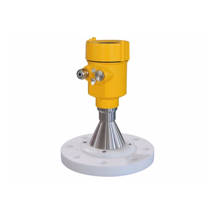
The length of the guided probe rod or cable of a guided wave radar level transmitter is fixed according to the operating conditions and generally cannot be interchanged in the same way as an ordinary non-contact radar. An excessively long guided probe increases installation and subsequent maintenance difficulty. The measuring distance is also limited and is usually shorter than that of an ordinary radar. Ordinary radar level transmitters are commonly used on tanks with heights of 30–40 m, and some models can reach 60 m. Before installation, the original instrument must be powered off in the control cabinet, and the positive and negative signal wires must be disconnected to facilitate subsequent insulation testing.
The installation position should avoid disturbed areas such as sewage inlets. Taking wastewater tanks as an example, polypropylene recycled rainwater drainage wastewater tanks, polypropylene granulation wastewater tanks, and polyethylene granulation wastewater tanks should preferably have the instrument installed near the center. For outdoor polyethylene refining rainwater drainage wastewater tanks, the instrument may be installed approximately 400 mm from the tank wall. Obstacles around the probe should be removed, and the protective enclosure support should preferably be made of 40 mm × 40 mm galvanized angle steel.
Install a 2-inch, Class 150 flange at the threaded connection above the transmitter, and make a circular opening approximately 50 mm in diameter at the bottom of the insulation box. First position the guided steel cable in the center, and then secure the flange to prevent the cable from contacting the wall of the insulation box and causing measurement deviation. Replace the signal cable with a 1 mm × 2 mm × 1.5 mm flame-retardant intrinsically safe cable. Use DN20 galvanized steel conduit with threaded connections for cable routing. After installation, perform an insulation test using a megohmmeter at 500 VDC for 60 seconds, with an insulation resistance of at least 20 MΩ. Tighten the instrument cable gland around the signal cable and ensure proper waterproof and explosion-proof protection. At the cable entry point, bend the excess signal cable downward and coil it into a circle approximately 100 mm in diameter to prevent moisture from traveling along the cable into the housing. Secure the shielding layer to the internal grounding terminal of the instrument housing. After confirming that the wiring is correct and that there is no unintended grounding, restore power and start the instrument.
For non-contact radar water level meters, installation focuses more on ensuring that the antenna is vertically aligned with the water surface, avoiding inlet and outlet flows and internal obstacles, and ensuring that the mounting support is rigid and properly protected against lightning.
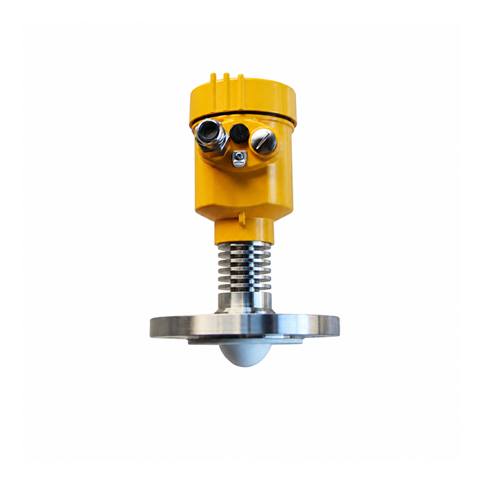
Advantages, Disadvantages, and Applications of Guided Wave Radar Level Transmitters
Compared with ordinary non-contact radar, guided wave radar level transmitters are more complicated in terms of selection and maintenance, and their measuring distance is shorter. Their main advantages are particularly evident under certain operating conditions:
More stable when the medium fluctuates significantly. When there is an agitator inside the tank or when the liquid surface fluctuates severely, a guided wave radar with the probe fixed at the bottom is generally more stable than an ordinary radar.
Suitable for small tanks. When installation space is limited or there are many internal obstructions, the beam of an ordinary radar can easily be affected, whereas guided wave radar is less affected by these conditions.
Better adaptability to low dielectric constants. The beam of an ordinary radar spreads during transmission, and when the dielectric constant of the medium is too low, the reflected signal may be weak and measurement may become unstable. With guided wave radar, the signal travels along the probe rod or cable, providing a more stable echo.
Engineering selection guidance: Guided wave radar should be considered first for applications involving severe liquid surface fluctuations, small vessels, or media with low dielectric constants. Non-contact radar is generally preferred for long measuring ranges, highly corrosive applications, or situations requiring frequent maintenance. METRAVON guided wave radar series supports both rod-type and cable-type configurations and can provide suitable solutions for turbulent media and small-tank applications.
Pulse Radar Level Transmitter Price and Operating Principle
Pulse radar level transmitters use microwave pulse measurement technology and can operate normally within industrial frequency bands. The beam energy is low, and the instrument can be installed on metal or non-metallic vessels and pipelines without causing harm to people or the environment. It is suitable for non-contact continuous measurement of liquids, slurries, and granular materials, especially in applications with large temperature or pressure variations, inert gases, or volatile substances.
The operating process consists of transmission, reflection, and reception. The antenna emits microwave pulses. When the pulses reach the surface of the measured medium, they are reflected. The reflected signals are then received and processed into a level signal. Because electromagnetic waves travel at extremely high speed, the measured time difference is very short.
Prices vary significantly depending on the manufacturer, model, operating frequency, antenna material, and explosion-proof rating. Different configurations have different prices, so the final selection should be based on the medium, operating environment, and required measurement accuracy. Contact METRAVON for application-specific pulse radar level transmitter pricing and technical confirmation.
Do Radar Level Transmitters Have a Blind Zone?
Under normal conditions, radar level transmitters have a blind zone. A commonly referenced value is approximately 0.3 m below the flange mounting surface, but the actual blind zone depends closely on instrument performance, operating frequency, antenna design, and installation angle. High-frequency radar, such as 80 GHz radar, usually has a smaller blind zone.
The blind zone is located in the upper, near-field area close to the instrument. The relevant parameters are generally preset at the factory and usually do not require readjustment. The maximum material or liquid level must not enter the blind zone; otherwise, measurement distortion may occur. During selection and installation, sufficient safety clearance must therefore be reserved according to the tank height and maximum operating level.
Features and Applications of High-Frequency Radar Level Transmitters
During operation, the antenna of a high-frequency radar level transmitter emits a relatively narrow microwave pulse beam. The beam travels toward the measured medium, reflects from its surface, and is received by the antenna. The returned signal is transmitted to the electronic circuitry, which automatically analyzes the signal and converts it into a level measurement. Because electromagnetic waves travel extremely quickly, the measurement process is very fast.
METRAVON high-frequency radar level transmitters feature compact antennas for easier installation, shorter wavelengths, and smaller measurement blind zones. They are generally less affected by corrosion, atmospheric water vapor, temperature variations, and pressure changes. Electromagnetic wave propagation is also relatively less affected by dusty environments. These instruments are suitable for complex operating conditions and offer convenient installation, simple operation, fast measurement, and high measurement accuracy.
Radar Level Transmitter Wiring Method
Radar level transmitters may use either DC or AC power supplies. Before wiring, check the instrument nameplate and labels, and prepare shielded twisted-pair cable with a conductor cross-sectional area of 0.5 mm²–2 mm². Depending on instrument wiring practices or applicable electrical regulations, separate cables and conduits may be required.
Operating procedure: Use a 2 mm hex key to loosen the locking screw, then use a screwdriver or suitable rod to unscrew the cover. Strip approximately 70 mm of insulation from the cable end and feed the cable into the instrument housing through the cable entry. Connect the wires according to the polarity markings on the terminal module. Ground the instrument according to local regulations. Tighten the cable gland to ensure a proper seal.
After completing the wiring, confirm that all connections are correct and that there is no unintended grounding before restoring power. The shielding layer should be reliably grounded, and the cable entry should be properly protected against water ingress.
FAQ
Q1: Can guided wave radar probe rods be interchanged?
A: Generally, no. The probe length is fixed according to the operating conditions. An excessively long probe increases installation and maintenance difficulty, so the length should be accurately matched during model selection.
Q2: Is guided wave radar suitable for long measuring ranges?
A: Its measuring distance is usually shorter than that of an ordinary radar. Ordinary radar is commonly used on tanks with heights of 30–40 m, and some models can reach 60 m. Guided wave radar is more suitable for short- to medium-range measurement.
Q3: Which type of radar should be selected for a medium with significant surface fluctuations?
A: When there is an agitator inside the tank or the liquid surface fluctuates severely, a guided wave radar with the probe fixed at the bottom is generally more stable than an ordinary radar.
Q4: Why is guided wave radar recommended for small tanks?
A: When installation space is limited or there are many internal obstructions, the beam of an ordinary radar can easily be affected. Guided wave radar transmits the signal along the probe rod or cable, providing better adaptability under these conditions.
Q5: How large is the blind zone of a radar level transmitter?
A: A commonly referenced blind zone is approximately 0.3 m below the flange surface, while high-frequency models usually have a smaller blind zone. The maximum material or liquid level must remain outside the blind zone.
Q6: Is pulse radar harmful to people?
A: The beam energy is low. Pulse radar can be installed on metal or non-metallic vessels and does not cause harm to people or the environment under normal operating conditions.
Q7: How does high-frequency radar perform in dusty environments?
A: Its shorter wavelength and more concentrated beam mean that dust generally has less influence on electromagnetic wave propagation, making it suitable for complex operating environments.
Q8: What cable specifications are recommended for wiring?
A: Shielded twisted-pair cable with a conductor cross-sectional area of 0.5 mm²–2 mm² is recommended, together with proper grounding and sealing.
Q9: What must be done before installing a guided wave radar?
A: Power off the instrument in the control cabinet and disconnect the positive and negative signal wires to facilitate subsequent insulation testing. The insulation resistance should be at least 20 MΩ.
Q10: How can I obtain a quotation for METRAVON pulse radar or high-frequency radar?
A: Provide information about the measured medium, measuring range, temperature, pressure, and installation conditions to obtain application-specific pricing and model selection support.
Conclusion
Guided wave radar level transmitter installation requires strict procedures for power isolation, avoidance of disturbed areas, mechanical fixing, and insulation testing. The guided probe length is fixed and the measuring range is limited, but guided wave radar provides greater stability and adaptability than ordinary radar in applications involving severe surface fluctuations, small tanks, and media with low dielectric constants. Pulse radar uses non-contact microwave pulse measurement, with low energy and a wide range of applications. Radar level transmitters generally have a near-field blind zone, and the maximum level must remain outside this area. High-frequency radar offers a compact antenna, a smaller blind zone, and strong resistance to environmental interference. Wiring should use shielded twisted-pair cable together with proper grounding and sealing.
METRAVON offers guided wave radar, pulse radar, and high-frequency radar series products and provides installation guidance, wiring recommendations, and application-based model selection support. If you require specific installation drawings, blind zone parameters, price confirmation, or model selection assistance, please provide detailed operating conditions, and we will assist in achieving reliable implementation.
Related resources
Radar level meters · Level measurement
Author: Arvin · Source: METRAVON Instruments
