


 Chinese
 Spanish
 Russian
 Portuguese
 French
 German
 Indonesian
 Thai
Thai Vietnamese
 Arabic
 Italian
 Turkish
 Polish
 Japanese

I. What Is a Guided Wave Radar Level Gauge?
A guided wave radar level gauge uses a probe rod or steel cable to guide electromagnetic waves toward the measured medium. When the radar signal reaches the surface of the medium, part of the signal is reflected and returns to the instrument along the probe rod or cable.
The instrument calculates the distance between the probe reference point and the surface of the medium based on the returned signal and then converts this distance into the actual liquid level.
Compared with conventional free-space radar, guided wave radar transmits most of its signal along the probe rod or cable, which concentrates the signal energy.
However, this structure also means that the following factors must be carefully considered during selection and installation:
Probe rod or cable length;
Vessel height;
Installation space;
Probe fixing method;
Whether agitation is present;
Whether the medium is prone to adhesion;
Whether obstacles are present around the probe.
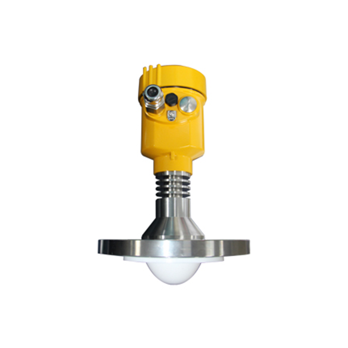
II. What Are the Features of Guided Wave Radar Level Gauges?
1. Suitable for Small Storage Tanks
Conventional free-space radar requires a certain amount of space for beam propagation.
In small tanks or installations with limited space, radar waves may be affected by tank walls or internal structures.
Because guided wave radar directs the signal along a probe rod or cable, it can provide favorable measurement conditions in certain small storage tanks.
2. Stable Measurement Under Significant Liquid Surface Fluctuation
If agitation or liquid surface fluctuation is present inside the vessel, a properly fixed probe rod or cable can provide a relatively stable propagation path for the radar signal.
For long cables or applications with strong liquid disturbance, bottom fixing can be evaluated according to the instrument installation requirements.
3. Advantages for Certain Low-Dielectric-Constant Media
Free-space radar signals must travel from the antenna to the medium surface and generate an effective reflected echo.
When the medium has weak reflection characteristics, the echo signal may be reduced.
Because guided wave radar concentrates electromagnetic energy along the probe rod or cable, it can provide a more stable signal for certain low-dielectric-constant media.
However, this does not mean that guided wave radar is completely unaffected by dielectric constant. The actual applicable range should still be confirmed from the specifications of the specific model.
III. What Are the Limitations of Guided Wave Radar Level Gauges?
Guided wave radar is not necessarily superior to free-space radar for every liquid level measurement project.
One obvious limitation is that:
The length of the probe rod or cable must match the actual vessel.
Longer probe rods or cables increase:
Transportation difficulty;
Installation difficulty;
Maintenance difficulty;
Mechanical fixing requirements.
The length of the probe rod or cable is generally determined according to the specific operating conditions, so probes from different projects may not necessarily be interchangeable.
In addition, the measurement range of guided wave radar is also limited by probe structure and mechanical installation conditions.
By comparison, free-space radar does not require a full-length probe to extend into the vessel and may be more suitable for certain long-distance measurement projects.
The specific maximum measurement range should be based on the datasheet of the corresponding model.
IV. What Should Be Considered When Installing a Guided Wave Radar Level Gauge?
1. Disconnect Power Before Removing or Installing the Instrument
Before replacing an existing level gauge or carrying out wiring work, disconnect the instrument power supply and handle the signal wiring according to on-site electrical safety requirements.
After installation, confirm that the wiring is correct before restoring power.
2. Avoid Inlet Areas
Guided wave radar should not be installed directly at wastewater inlets, material feed inlets, or locations subject to strong liquid impact.
Incoming liquid may cause the cable to swing and may also create significant surface fluctuation, affecting measurement.
3. Avoid Contact Between the Cable and Surrounding Structures
The guided wave cable should be kept in a suitable position and should avoid direct contact with:
Pool walls;
Tank walls;
Protective enclosures;
Pipes;
Supports;
Other metal structures.
Contact between the cable and surrounding metal structures may generate additional reflections and can also cause mechanical wear.
V. How Should Waterproofing Be Handled for Outdoor Guided Wave Radar Installations?
For outdoor installations, particular attention should be paid to the instrument cable entry.
During installation:
Securely tighten the cable gland;
Seal conduit connections properly;
Maintain the sealing integrity of the instrument enclosure;
Provide a drip loop at the cable entry;
Handle the cable shield according to electrical requirements.
Before the cable enters the instrument, it can first be bent downward so that rainwater or condensation drips from the lowest point, reducing the risk of water traveling along the cable into the instrument.
This measure is especially important for open wastewater tanks, storage tanks, and other high-humidity environments.
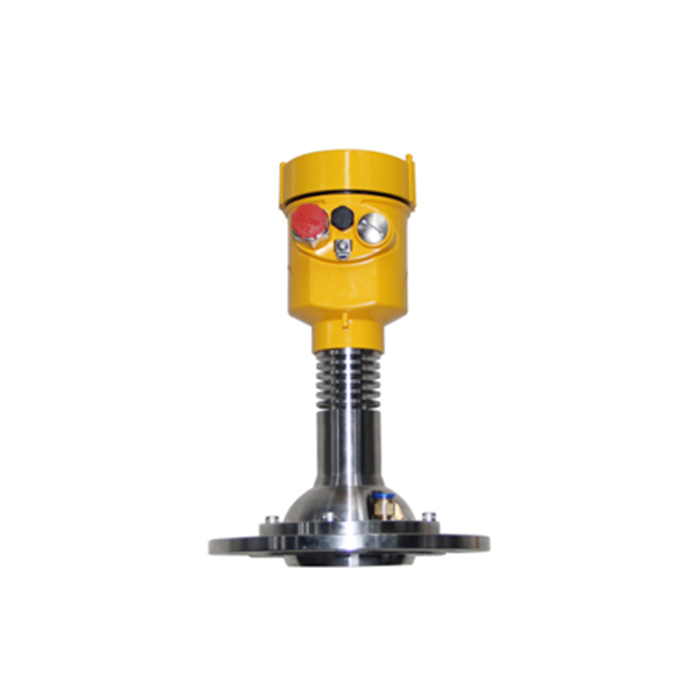
VI. What Should Be Considered During Signal Cable Installation and Insulation Testing?
Some engineering projects perform insulation testing after signal cable installation is completed.
For example, certain project specifications may use:
Test voltage: 500 VDC;
Test duration: 60 s;
Insulation resistance: ≥20 MΩ.
These parameters are specific engineering requirements and are not universal standards for all guided wave radar level gauge projects.
Before performing an insulation test, confirm that the instrument electronics have been disconnected from the test circuit. Testing should be carried out according to the instrument manual and project electrical specifications to avoid damaging electronic equipment with excessive test voltage.
VII. How Should a Radar Level Gauge Be Wired?
Different radar level gauge models may use DC or AC power supplies. Therefore, before wiring, first check:
Instrument nameplate;
Supply voltage;
Power supply type;
Certification requirements;
Terminal definitions;
Signal polarity;
Grounding terminal.
Some product installation documents recommend shielded twisted-pair cable with a conductor cross-sectional area of approximately 0.5 mm²–2 mm².
The actual cable specification should also be determined according to the power supply method, cable distance, and on-site electrical standards.
Typical wiring steps include:
Disconnect the instrument power supply;
Check the nameplate and wiring diagram;
Open the terminal compartment;
Feed the cable through the cable entry;
Connect the wires according to the terminal markings;
Handle shielding and grounding according to requirements;
Check polarity;
Tighten the cable gland;
Restore power after confirming the enclosure is properly sealed.
The specific tools, wire stripping length, and terminal operating method should be based on the installation manual for the corresponding model.
VIII. How Should a Radar Level Gauge Model Be Selected?
Radar level gauges are available with a variety of antenna and structural designs, including:
Horn antennas;
Parabolic antennas;
Array antennas;
Rod antennas;
Drop-shaped antennas;
Planar antennas;
Hygienic designs.
Different models are suitable for different operating conditions.
The following factors should be carefully confirmed during selection:
| Operating Condition | Key Consideration |
|---|---|
| Corrosive Volatile Gases | Antenna and process materials |
| Large Amounts of Water Vapor | Radar structure and site conditions |
| Dust | Echo strength and antenna type |
| Crystallizing Media | Risk of material buildup on the probe |
| Large Amounts of Foam | Actual echo conditions |
| Liquid Surface Fluctuation | Installation position and signal processing |
| Powder Materials | Material surface condition and dust |
| Granular Materials | Measurement range and antenna |
| Corrosive Liquids | Material compatibility |
| High-Viscosity Media | Adhesion and maintenance |
Therefore, a radar level gauge model should not be selected based only on the required measurement range.
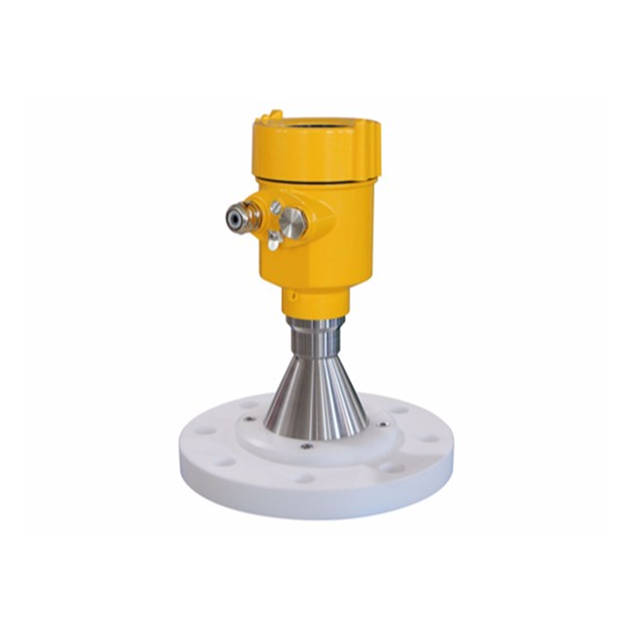
IX. What Should Be Considered When Purchasing an 80GHz Radar Level Gauge?
80GHz radar level gauges generally use Frequency-Modulated Continuous-Wave (FMCW) technology.
During each frequency sweep cycle, the instrument transmits a radar signal whose frequency changes continuously. After the echo returns, it forms a frequency difference relative to the current transmitted signal. The instrument calculates the target distance based on this frequency difference.
Some 80GHz product specifications may provide:
Approximately 1° narrow beam;
Millimeter-level measurement accuracy;
Fast echo processing;
Echo curve display;
Multilingual operating interface;
Applications involving dust and steam.
However, these parameters are specific to individual products and should not be regarded as universal specifications for all 80GHz radar instruments.
For example:
1° beam angle;
1 mm accuracy;
5 ms measurement cycle.
All of these should be confirmed from the datasheet of the corresponding model and under the specified test conditions.
When purchasing an 80GHz radar level gauge, the following parameters should be compared carefully:
Maximum measurement range;
Measurement accuracy;
Beam angle;
Antenna structure;
Process temperature;
Process pressure;
Dust and steam conditions;
Installation connection;
Commissioning method.
X. What Is the Purpose of Radar Level Gauge Standards?
Standards related to radar level gauges are mainly used to regulate product design, manufacturing, testing, installation, and industrial applications.
For actual engineering projects, it is more important to confirm:
Which standards are required by the project;
Whether the product meets the corresponding safety requirements;
Whether explosion protection is involved;
Whether environmental protection requirements apply;
Whether the electrical installation meets the required standards;
Whether the relevant certifications satisfy project requirements.
Standards are an important basis for engineering design and product application, but they are not the only criterion for evaluating instrument performance.
FAQ
Q1: What Is the Main Difference Between Guided Wave Radar and Conventional Radar?
Guided wave radar transmits radar signals along a probe rod or steel cable, while free-space radar transmits radar waves through the open space inside the vessel toward the surface of the medium. Therefore, the two instrument types differ significantly in installation structure and suitable operating conditions.
Q2: Is Guided Wave Radar Suitable for Long-Distance Measurement?
The actual measurement range of guided wave radar is limited by probe rod or cable length, mechanical installation, and the specific model. For long-distance level measurement, the actual specifications of both guided wave radar and free-space radar should be compared before selection.
Q3: Is Guided Wave Radar Completely Unaffected by Dielectric Constant?
No. The guided wave structure concentrates radar energy and can provide advantages for certain low-dielectric-constant media, but the dielectric characteristics of the medium still affect the returned echo.
Q4: Why Should the Steel Cable Not Contact the Tank Wall?
Contact between the steel cable and the tank wall may generate additional reflections, while long-term friction may also cause mechanical wear and affect measurement stability.
Q5: Does Every 80GHz Radar Level Gauge Provide 1 mm Accuracy?
No. A 1 mm accuracy specification applies only to certain models under specified conditions. Actual accuracy must be confirmed according to the specific product and application conditions.
Q6: Is Guided Wave Radar Maintenance-Free?
It should not be considered completely maintenance-free. For viscous, crystallizing, or easily adhering media, the condition of the probe rod or cable, instrument sealing, and electrical connections should still be checked periodically.
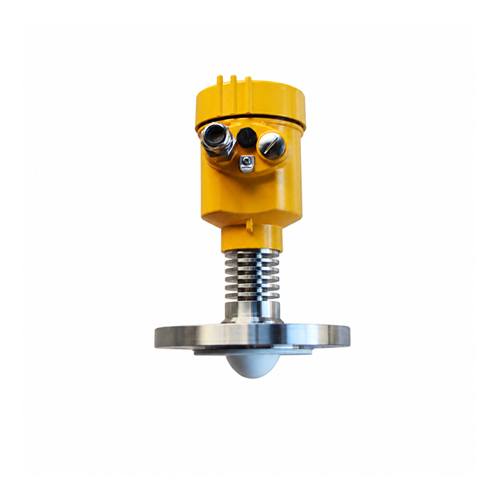
Conclusion
Guided wave radar level gauges guide electromagnetic signals along a probe rod or cable and are well suited to small storage tanks, fluctuating liquid surfaces, and certain low-dielectric-constant media.
However, the probe rod or cable length must be determined according to site conditions, and longer probes increase installation and maintenance difficulty.
During installation, particular attention should be paid to:
Inlet position, clearance between the cable and tank wall, mechanical fixing, cable waterproofing, shielding and grounding, and wiring inspection.
When selecting guided wave radar or 80GHz free-space radar, the following factors should be considered comprehensively:
Measurement range, medium, dielectric characteristics, dust, steam, foam, viscosity, temperature, pressure, and installation space.
Specific dimensions, cable specifications, insulation test conditions, and 80GHz radar performance parameters should be based on the datasheet, installation instructions, and project technical specifications of the corresponding instrument.
