


 Chinese
 Spanish
 Russian
 Portuguese
 French
 German
 Indonesian
 Thai
Thai Vietnamese
 Arabic
 Italian
 Turkish
 Polish
 Japanese

In industrial process control, chemical tank farm management, and dusty silo monitoring, high-precision continuous measurement of level (liquid level / material level) directly determines production safety and system automation efficiency. High-frequency radar level meters (including high-frequency pulse radar liquid level meters and high-frequency pulse radar material level meters) use a 25GHz/26GHz high-frequency transmission frequency as their core technology, with a maximum measuring range of up to 30 meters, and support multiple installation methods such as threaded and flange connections.
This article systematically integrates the working principle, core features and advantages, flange installation specifications, typical extreme operating-condition solutions, and on-site troubleshooting techniques of high-frequency radar level meters, providing a one-stop engineering guide for system integrators, engineering contractors (EPCs), and procurement teams.
I. Working Principle and Measurement Calculation
METRAVON high-frequency radar level meters adopt a high-frequency microstrip circuit design. The internal circuit generates 25GHz/26GHz high-frequency microwave pulse signals.
Pulse Transmission: Based on the high-frequency waveguide design principle, microwave pulses are transmitted toward the surface of the measured medium through the end of the PTFE (polytetrafluoroethylene) highly corrosion-resistant antenna.
Signal Reflection: After the transmitted pulse reaches the surface of the measured medium, part of the microwave energy is reflected back to the antenna and received because of the abrupt change in the dielectric constant of the medium.
Time-Expansion Calculation: The instrument has a built-in intelligent microprocessor that uses the time-expansion principle (Time-of-Flight / time travel method) to accurately calculate the time interval Δt between the transmitted pulse and the received pulse.
Distance and Level Calculation: Based on the electromagnetic wave propagation speed c, the distance from the antenna reference plane to the medium surface is calculated as D = (c × Δt) / 2. This value is then combined with the total vessel height to calculate the real-time level.
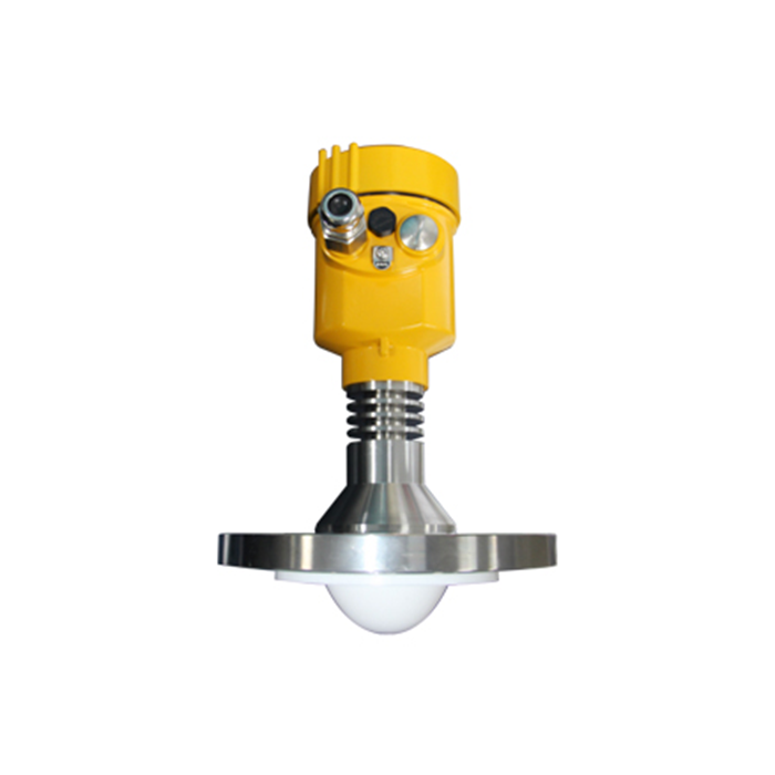
II. Core Features and Outstanding Advantages Compared with Low-Frequency Radar
Compared with traditional 6GHz low-frequency pulse radar, 25GHz/26GHz high-frequency radar level meters demonstrate significant advantages in physical characteristics and adaptability to harsh environments:
| Performance Dimension | Core Advantages of High-Frequency Radar (25GHz / 26GHz) | Limitations of Low-Frequency Radar (6GHz) |
|---|---|---|
| Beam Angle and Energy | Narrow beam angle and highly concentrated energy, strong echo signals, and easy avoidance of interference from internal tank obstacles. | Wide beam angle; energy is easily scattered and strikes the tank wall, generating false echoes. |
| Bulk Solid Level Reflection | Short wavelength (26GHz wavelength is approximately 11mm), providing excellent reflection from inclined bulk solid surfaces. | Long wavelengths suffer serious reflected-signal attenuation on inclined bulk material surfaces. |
| Small Vessel Adaptability | High frequency, compact antenna, small dead zone, perfectly suited for small-diameter and low-height storage tanks. | Large antenna dimensions impose high requirements on installation space and vessel openings. |
| Resistance to Contamination and Condensation | Compact antenna makes it easy to add a PTFE dust cover / anti-condensation surface, reducing the impact of contamination and water-vapor accumulation. | The antenna is more prone to material buildup and water-vapor accumulation, resulting in severe microwave signal attenuation. |
| Isolated Non-Contact Measurement | Excellent directionality allows measurement through a simple non-metallic isolation window from outside the vessel. | Microwave energy is dispersed, making stable transmission through isolation materials more difficult. |
| Environmental Tolerance | Unaffected by strong corrosion, foam, water vapor, temperature, and pressure variations; high dust concentrations cause almost no interference. | More susceptible to complex vapor-phase conditions and interference from the medium surface. |
III. Flange Installation Precautions and Echo Adjustment Specifications
As the core process connection between the radar level meter and the vessel, the mounting orientation and angle of the flange directly determine echo quality:
1. Orientation Rules for the Flange Indicator Mark
Conventional Storage Tank Installation: The flange indicator mark should point precisely toward the tank wall or the geometric center of the storage tank so that the microwave beam avoids internal ladders, pipes, and other structures.
Stilling Well Installation: The flange mark must point precisely toward the side of the stilling well where the opening (vent hole / balance hole) is located.
Bypass Chamber Installation: The flange mark must point precisely toward the side where the upper and lower connecting pipes communicate with the storage tank.
2. Physical Adjustment of Interference Echoes and Suppression Storage
Signal Diagnosis: During radar operation, the amplitude of the echo signal directly reflects whether the installation position is appropriate. A low echo-signal amplitude usually indicates obstruction or orientation deviation.
Step-by-Step Flange Rotation Adjustment: During commissioning, rotate the flange clockwise or counterclockwise one bolt-hole position at a time, observe changes in the waveform, and use microwave polarization characteristics to minimize interference echoes.
False Echo Suppression: Use the instrument's built-in echo-learning function to store static interference generated by fixed metal structures inside the tank in the suppression mask, thereby achieving optimal measurement performance.
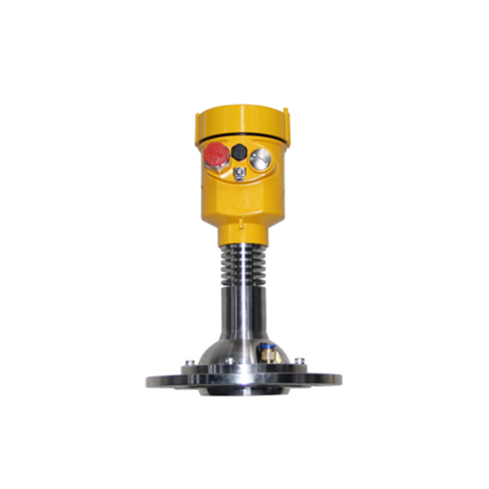
IV. Three Typical Extreme Operating Conditions: Combined Hardware and Software Solutions
For complex environments commonly encountered in industrial applications, METRAVON summarizes the following engineering configuration and installation solutions:
Cement / Power Plant Clinker Silo with Heavy Dust (30m-High Silo):
Solution: 26GHz high-frequency radar + parabolic antenna (or antenna with PTFE dust cover) + compressed-air timed purging flange assembly (using 0.2MPa to 0.4MPa instrument air), enabling automatic cleaning of the antenna surface and long-term maintenance-free continuous measurement.
Highly Corrosive Chemical Reactor with Severe Agitation and Steam:
Solution: Use a fully PTFE-encapsulated corrosion-resistant antenna with no exposed metal; combine it with a stilling well to physically isolate liquid-surface surges, or enable the METRAVON instrument's built-in dynamic false-echo suppression algorithm to filter interference from agitator blades.
Food / Pharmaceutical Sterile Tank with CIP/SIP High-Temperature Cleaning:
Solution: Use a Tri-Clamp sanitary quick-connect flange + polished PTFE flat antenna, with no structural dead zones and easy online cleaning at temperatures above 130°C.
V. B2B Procurement Selection Checklist and On-Site Rapid Troubleshooting Guide
1. Engineering Selection Checklist
Check the Dielectric Constant (Er): If the medium has Er > 3 (water, acidic or alkaline liquids), a standard antenna is sufficient; if Er < 2 (diesel, polyethylene powder), a high-gain parabolic antenna should be selected or guided-wave radar should be used instead.
Check the Installation Nozzle Proportion: The bottom of the antenna transmission surface must extend at least 10mm beyond the inner wall of the installation nozzle to prevent strong interference reflections from the nozzle wall.
Avoid the Dead Zone and Filling Inlet: The installation position should be more than 200mm from the tank wall (and greater than 1/6 of the tank diameter), and the instrument must never be installed directly above the filling inlet.
2. Common On-Site Diagnostic Troubleshooting Table
| On-Site Abnormal Phenomenon | Possible Cause Analysis | METRAVON Engineer Recommended Solution Steps |
|---|---|---|
| Display Locked at Maximum Value (Full Silo / Full Tank) | Severe condensation / buildup on the antenna, or strong reflections generated inside the installation nozzle. | 1. Remove the instrument and clean dust or water vapor from the antenna surface; 2. Ensure that the bottom of the antenna extends beyond the inner wall of the installation nozzle. |
| Measured Value Fluctuates Significantly When the Agitator Operates | The microwave beam directly illuminates the agitator blades or anti-surge baffle. | 1. Loosen the flange bolts and rotate the flange by one bolt-hole position for adjustment; 2. Perform “false echo learning and storage” again. |
| Output Signal Lost or Weak Echo Indicated | Echo amplitude is below the recognition threshold due to a low dielectric constant or an excessively steep material surface angle. | 1. Check whether the flange mark points precisely toward the center of the tank; 2. Adjust the beam angle or replace the antenna with a high-gain parabolic antenna. |
VI. Industrial 4.0 Bus Integration and Key Parameters
Communication and Bus Integration: Native support for 4-20mA + HART protocol and RS-485 Modbus RTU industrial bus enables seamless direct connection to mainstream PLCs and DCS systems such as Siemens and Mitsubishi, as well as industrial IoT platforms. Optional 4G / NB-IoT modules can be selected to enable MQTT protocol data transmission to the cloud.
Key Technical Parameters: Measuring range: 0 meters to 30 meters; accuracy: ±3mm or ±5mm; process temperature: -40°C to +200°C (high-temperature customized versions available up to +400°C); process pressure: -0.1MPa to 4.0MPa; available with Ex d IIC T6 Gb (flameproof) / Ex ia IIC T6 Ga (intrinsically safe) dual explosion-proof certifications.
VII. Service and Technical Support
To ensure project progress and stable normal operation of equipment in the field, METRAVON provides a dedicated 10-hour instrumentation service hotline, with technical engineers responding promptly to questions and solving practical issues involving product selection, flange positioning, Modbus protocol commissioning, echo storage configuration, and other on-site operations.
Engineering Designer and Procurement Resource Support
Need to obtain METRAVON high-frequency radar level meter CAD/STP assembly drawings, a Modbus register address allocation table, or a customized quotation for your project?
Contact the METRAVON engineering and technical team. We will provide you with one-on-one expert product selection support!
