


 Chinese
 Spanish
 Russian
 Portuguese
 French
 German
 Indonesian
 Thai
 Vietnamese
 Arabic
 Italian
 Turkish
 Polish
 Japanese



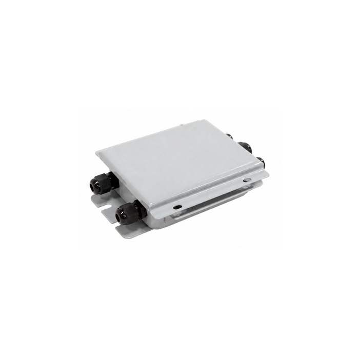
METRAVON MV-WA0005 is a load cell junction box offered with excitation-trim or signal-trim configurations. The catalogue enclosure measures 153 x 112 x 36 mm. Select the adjustment circuit against the scale's wiring and commissioning procedure; confirm the enclosure material, finish and mounting drawing in the quotation before approving a replacement.
Choose the trim circuit before the enclosure
The A1 configuration adjusts excitation, while A2 adjusts the signal contribution. Both concern balancing connected analog load cells, but the electrical arrangements differ. Identify the existing circuit and indicator connections before changing between them. A similar enclosure cannot establish that the internal board is a like-for-like replacement.
| Configuration item | Selection information |
|---|---|
| A1 adjustment | Excitation trim |
| A2 adjustment | Signal trim |
| Catalogue overall dimensions | 153 x 112 x 36 mm |
| Enclosure material and finish | Obtain written confirmation for the quoted configuration before ordering. |
| Terminal layout | Check the sensor connections and indicator wiring against the supplied diagram. |
Enclosure dimensions are a preliminary space check, not a drilling template. Request the hole positions, cable-entry details and lid clearance. For a project that specifically requires 304 stainless steel and signal trim, review MV-WA0003; do not infer the material of MV-WA0005 from a similar photograph or size.
Resolve wiring and corner errors separately
Record each sensor's terminal assignment before disconnecting the old box. Use the replacement diagram to identify excitation, signal, any sense connections and shield termination. Cable colours are not a reliable substitute for that diagram, especially when the installation contains replacement sensors from different production periods.
Before adjusting channel balance, inspect the scale for restricted movement, contact with adjacent structures or damaged supports. Then follow the scale's corner-test procedure with a consistent test load and documented positions. Recheck the overall calibration after trimming. The junction-box selection and adjustment guide covers this sequence in more detail.
Circuit and enclosure questions
Q1. Does a cable-entry count specify four-wire sensor compatibility?
No. The number of entries describes the enclosure arrangement; sensor conductor count describes the electrical connection. Obtain the terminal diagram and identify any sense-wire requirements before deciding whether the box suits the installed load cells.
Q2. Can this box deliver a 4-20 mA signal to a PLC?
The listed adjustment functions do not establish a current-loop output. If the PLC requires 4-20 mA, specify a compatible weighing instrument or transmitter between the analog sensor circuit and the PLC. Include that device in the wiring review rather than treating a junction box as a signal converter.
Q3. What must be confirmed for a corrosive or wet location?
Obtain the actual housing material, coating where applicable, lid seal and gland specifications. Provide the cleaning chemicals and exposure conditions. Neither the metal appearance nor the box dimensions establish corrosion resistance or an ingress-protection rating.
Ask METRAVON to confirm an MV-WA0005 configuration using the existing box diagram, sensor count, indicator model and required trim method. Include photographs of the mounting space and terminals so that circuit suitability and mechanical fit can both be checked.
