


 Chinese
 Spanish
 Russian
 Portuguese
 French
 German
 Indonesian
 Thai
 Vietnamese
 Arabic
 Italian
 Turkish
 Polish
 Japanese



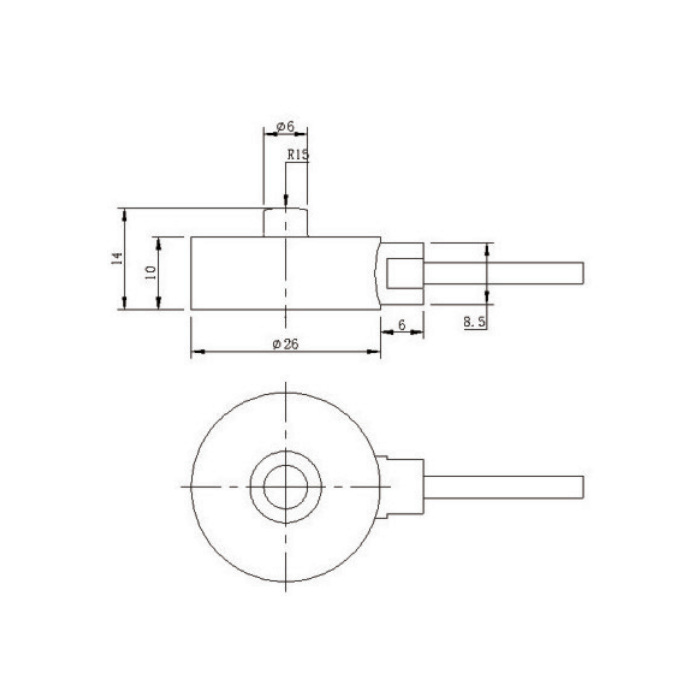
METRAVON MV-LC0236 is a button compression load cell with a 26 mm diameter body and 14 mm overall height. Force is introduced at the raised central contact, not through a transverse pin. For a compact pressing or contact-force fixture, the main design questions are how the base is supported, where the moving part touches and whether lateral force can reach the sensor.
A rounded contact still needs controlled alignment
The drawing shows a 6 mm central button with an R15 contact profile. That geometry does not make the sensor immune to an off-centre load or authorize side loading. Review the mating surface, material and movement across the full machine stroke. A sliding or tilted contact can change the load introduction even when the displayed force remains below the nominal rating.
MV-LC0236 selection data
Select a discrete rating rather than treating 50 N-5 kN as an adjustable measuring range of one unit. Include the force applied during fixture closure, not only the force reported during the test. A higher rating provides less signal per newton at the same excitation and nominal sensitivity; confirm that the reader can resolve the minimum force that matters to the process.
| Item | Value | Use / fit |
|---|---|---|
| Available ratings | 50, 100, 200, 500 N; 1, 2, 5 kN | State the selected option on the order. |
| Body / overall envelope | 26 mm diameter / 14 mm height | Body height is 10 mm; allow additional cable and contact clearance. |
| Nominal output | 1 mV/V; +/-10% | Requires a bridge input, not a standard 4-20 mA input. |
| Input / output resistance | 350 +/-30 / 350 +/-30 ohms | Confirm the actual reader compatibility; both tolerances matter. |
| Creep | +/-0.05% / 30 min | Define hold time and permitted indication change for the application. |
| Excitation | 5 V reference; 1-15 V operating | Keep the input and excitation settings with the calibration record. |
| Service temperature | -10 to +50 deg C | Nominal temperature range is -10 to +40 deg C. |
| Material / protection | Stainless steel / IP67 | Does not replace an assessment of the assembled fixture exposure. |
Avoid mounting and cable loads that alter zero
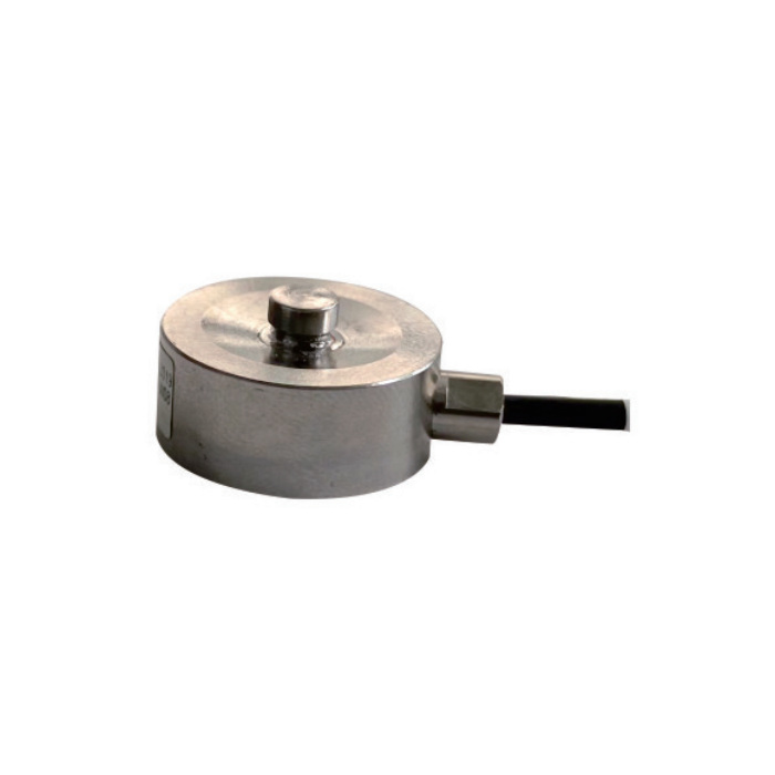
Support the base on the intended bearing surface and agree a retention method from the assembly drawing. Do not assume fixing holes or a clamp arrangement from the round outline alone. Route the cable so that a moving guard, actuator or cable carrier cannot pull on the sensor during measurement. Compare unloaded readings before and after the surrounding hardware is secured.
Acceptance should reproduce the contact cycle
Run repeated loading and unloading with the final moving member, support and reader. Record zero return and readings at the forces relevant to the process, including any sustained hold. For a force limit used by machine controls, verify the entire indication and decision chain separately; the sensor catalogue does not establish a safety function or a machine stopping performance.
For a smaller body diameter, compare the 20 mm MV-LC0233 compression load cell and review its different height and output-resistance tolerance.
Questions before ordering
Q1. Does force divided by the button area give process pressure?
Not automatically. The button transfers force into the sensor; it does not define the effective process area of a press tool, diaphragm or other mechanism. A pressure calculation needs a justified effective area and a verified mechanical load path.
Q2. Can a generic load-cell amplifier read this model?
Check more than the connector. The amplifier must support the bridge resistance, excitation and 1 mV/V signal, with sufficient zero and span adjustment for the supplied unit. Confirm filtering and response against the real force cycle before relying on peak readings.
