


 Chinese
 Spanish
 Russian
 Portuguese
 French
 German
 Indonesian
 Thai
 Vietnamese
 Arabic
 Italian
 Turkish
 Polish
 Japanese



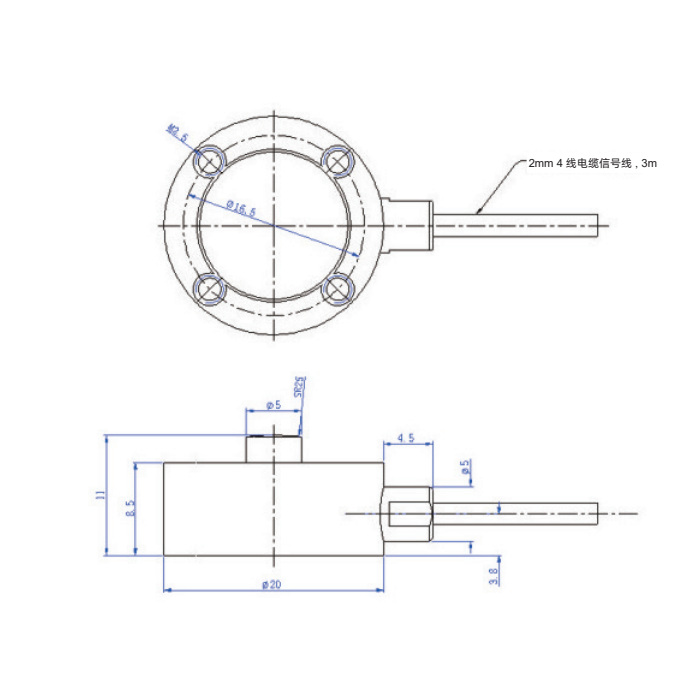
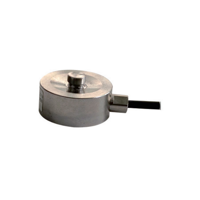
METRAVON MV-LC0233 measures compression through a small central loading button. The 20 mm diameter body fits compact force-measuring assemblies, but the available space must also accommodate the loading member, a rigid supporting surface and cable routing. It is a button-type load cell, not a sensing pin for a clevis or sheave.
Start with the contact, not just the rated force
The force should enter through the button along the intended measuring axis. A fixture that presses against the surrounding body, rocks on the base or pulls sideways on the button creates a different load path from the one being measured. Send a section drawing showing the moving contact, the sensor support and the intended retention method before machining the fixture.
MV-LC0233 dimensions and electrical requirements
The drawing distinguishes the 8.5 mm body height from the 11 mm overall height to the top of the button. Using the lower dimension as the assembled envelope would leave insufficient room for the loading contact. The central button is 5 mm in diameter; the mating component needs its own contact and alignment review.
| Item | Value | Use / fit |
|---|---|---|
| Rated force options | 50, 100, 200, 500 N; 1, 2, 5 kN | Choose one rating, including the expected assembly preload. |
| Envelope | 20 mm diameter; 11 mm overall height | Body height alone is 8.5 mm; add space for the mating contact. |
| Sensitivity | 1 mV/V; +/-10% | Set gain for the individual sensor rather than assuming exactly 1 mV/V. |
| Nonlinearity / hysteresis / repeatability | Each +/-0.1% Cn | Separate catalogue characteristics; not an installed-system accuracy guarantee. |
| Excitation | 5 V reference; 1-15 V operating | Confirm input range and excitation capability of the reader. |
| Input / output resistance | 350 +/-30 / 350 +/-3 ohms | Check bridge loading when choosing an instrument. |
| Construction / protection | Stainless steel; IP67 | Cable entry and the completed installation still require environmental review. |
Read the millivolt bridge with a suitable input
At the 5 V reference excitation, 1 mV/V nominal sensitivity corresponds to about 5 mV at rated force, before the stated sensitivity tolerance. This is not a 0-5 V signal and cannot be wired straight into a standard voltage or current input. A bridge-capable instrument provides excitation and reads the differential signal; a separate conditioner is needed when the control system requires 4-20 mA or another interface.
Commission with the actual loading member
Record the unloaded value after securing the base and arranging the cable. Apply a known compressive force through the final contact, remove it, and repeat at agreed points within the working range. If zero changes when a cover or cable clamp is tightened, investigate the mounting before adjusting calibration. Calibration of a loose sensor alone does not establish the performance of the completed fixture.
Compare the 4.5 mm low-profile MV-LC0234 only after checking its lower maximum rating and different error specifications.
Questions before ordering
Q1. Can it measure a suspended tensile load?
The documented loading direction is compression. Do not attach a hanging load to the body or reinterpret the fixing features as a tension connection. For a threaded pull/push fixture, review MV-LC0235 and its capacity-dependent connection drawing instead.
Q2. Which cable colours connect to the bridge reader?
The wiring diagram assigns red to excitation positive, black to excitation negative, green to signal positive and white to signal negative. Yellow identifies the shield. Verify the supplied cable documentation and the instrument bonding arrangement before energising the bridge.
Q3. What should accompany a quotation request?
Include the chosen nominal force, minimum force of interest, loading-contact drawing, available height, expected shock loads, operating temperature and the proposed reader. State whether the cable will move during a measurement; cable forces can matter in a small compression assembly.
