


 Chinese
 Spanish
 Russian
 Portuguese
 French
 German
 Indonesian
 Thai
 Vietnamese
 Arabic
 Italian
 Turkish
 Polish
 Japanese



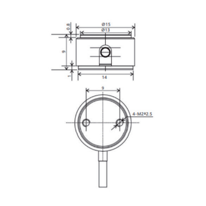
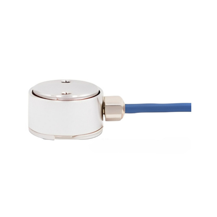
METRAVON MV-LC0232 is a low-force compression load cell with 10, 20, 50, 100, 200 and 500 N rating options. Its short circular housing differs from a threaded pull/push sensor: the assembly must deliver force to the designated compression face while supporting the base. The 15 mm outer diameter is a useful space check, but not a complete mounting specification.
Identify the loaded face and the restrained surface
Use the outline and force-direction drawing to define which surface receives the load and which surface supports the sensor. Keep retainers and nearby parts from forming an unintended parallel load path. The drawing includes small fixing features; obtain the full mounting detail and engagement requirement before making the base rather than inferring a clamp design from a photograph.
Small forces make cable and contact effects visible
When selecting the lower ranges, include the weight of the contact part and any fixture preload. Support the cable so normal machine movement cannot pull on the housing or change the unloaded reading. Test the final contact position, not just a loose unit on a bench, because a tilted or rubbing mating part can alter the force reaching the sensor.
Separate analogue acquisition from process communication
The sensor produces a 1 mV/V nominal bridge output and uses a 5 V reference excitation. It does not directly provide 4-20 mA or a serial data stream. A bridge instrument or conditioner must supply excitation, measure the differential voltage and establish the scale factor. If the project needs PLC or data logger integration, include that equipment in the enquiry so the output interface is selected explicitly.
| Item | Value | Use / fit |
|---|---|---|
| Rated force options | 10, 20, 50, 100, 200, 500 N | A separate selected range, not an adjustable capacity setting. |
| Nominal sensitivity | 1 mV/V; +/-10% | Use individual calibration to set span. |
| Nonlinearity / hysteresis / repeatability | Each +/-0.2% Cn | Review against the required force decision, not an assumed accuracy class. |
| Creep / DR | +/-0.2% / 30 min | Check sustained compression if the process includes a hold. |
| Zero balance | +/-0.05 mV/V | The reader needs sufficient initial offset adjustment. |
| Bridge resistance, input / output | 350 +/-30 / 350 +/-3 ohms | Match the measuring input and excitation source. |
| Service temperature | -10 to +50 deg C | Nominal temperature range is -10 to +40 deg C. |
| Construction | Stainless steel; IP66 | Confirm sealing of the completed installation separately. |
Verify the repeatable force that the process needs
Commission at representative loads within the selected rating, using the final support, contact and cable arrangement. Record repeated loading, unloading and zero return. Where the process holds force, include the actual duration in the check; the catalogue creep/DR figure is specified over 30 minutes and is not a substitute for the agreed process acceptance limit.
If the fixture must transmit axial tension, review MV-LC0231 and design around its threaded connections.
Mounting and measurement questions
Q1. Can this sensor replace a threaded tension/compression unit?
Not as a direct mechanical substitute. MV-LC0232 is documented for compression, whereas a threaded bidirectional assembly carries load through its attachments. A replacement requires a new load-path review, not merely matching the force rating.
Q2. What should be supplied for a mounting review?
Send a cross-section showing the contact face, supporting base, retention and moving parts. Add the selected rating, expected preload, cable route, temperature and bridge-reader model. State the minimum force that must be distinguished so the signal chain can be assessed at that point.
