


 Chinese
 Spanish
 Russian
 Portuguese
 French
 German
 Indonesian
 Thai
 Vietnamese
 Arabic
 Italian
 Turkish
 Polish
 Japanese



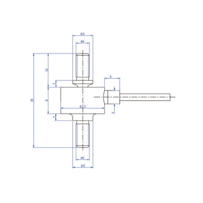
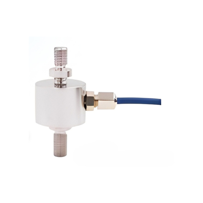
METRAVON MV-LC0231 is a miniature threaded tension/compression load cell for small axial pull and push measurements. Available ratings are 10, 20, 50, 100, 200 and 500 N. The drawing shows a 13 mm body and opposing M4 connections; adapters and the attached test parts must be considered when assessing both the mounting space and the force already acting on the sensor.
Select the small-force range from the whole test cycle
A test may begin with fixture weight or assembly preload before the specimen is loaded. With a 10 N version, those forces can consume a meaningful part of the range. State the smallest useful force, the largest expected force in each direction and any closing impact. Choosing 500 N for every test reduces the bridge signal produced by the same small force.
| Item | Value | Use / fit |
|---|---|---|
| Rated choices | 10, 20, 50, 100, 200, 500 N | Specify one rating and the required measurement direction or directions. |
| Connections | M4 at both ends | Confirm the selected drawing before making mating parts. |
| Sensitivity tolerance | +/-10% of nominal 1 mV/V | Calibrate using the supplied sensor, not a nominal gain alone. |
| Nonlinearity / hysteresis / repeatability | Each +/-0.2% Cn | Not a combined error figure for the test machine. |
| Creep / DR | +/-0.2% / 30 min | Define hold duration for constant-force tests. |
| Input / output resistance | 350 +/-30 / 350 +/-3 ohms | Check the instrument bridge specification and wiring. |
| Housing / protection | Stainless steel / IP66 | Assess cable routing and the assembled connection exposure. |
Make the two attachment axes coincide
The threaded ends are intended to transmit axial load. Misaligned rigid adapters can impose bending even when the intended test is purely tensile. Check thread engagement and the assembly method without turning the sensor body against an already locked opposite connection. Leave the side cable free of strain from moving fixtures, and include the actual adapters during commissioning.
Calculate signal levels before selecting the amplifier
The nominal sensitivity is 1 mV/V, so the full-scale signal at the 5 V reference excitation is approximately 5 mV. For an ideal linear 500 N version, 10 N is only 2% of range, or about 0.1 mV at that excitation before offset and sensitivity tolerance. This calculation illustrates input-range needs; it is not a stated resolution or measurement uncertainty.
Check both signs instead of calibrating one end point
For alternating pull and push measurements, establish the sign convention and check reference forces in both directions. Include unloading and return through zero. The listed nonlinearity, hysteresis and repeatability are individual sensor characteristics; acceptable results for the assembled test fixture must be agreed from the application requirements.
Compare MV-LC0229 where M3 attachments and 10-100 N options better match an existing small-force fixture; it has different geometry and sensitivity.
Questions about pull and push testing
Q1. Will zeroing remove the weight of the grips?
It can remove the displayed offset, but the grips still apply mechanical force. Include their weight and any preload when checking the sensor range, especially on a vertical low-force fixture.
Q2. Can the bridge connect directly to an RS485 data logger?
Only if a compatible bridge acquisition stage is provided. RS485 is not the documented sensor output. Specify a bridge reader or conditioner, then verify the communication protocol and channel scaling of that separate device.
Q3. Which test details are needed for a quote?
Provide the desired rating, tensile and compressive working forces, adapter drawing, required cable movement, hold time and measuring instrument. Include the intended acceptance procedure so the quoted sensor and calibration scope address the actual test.
