


 Chinese
 Spanish
 Russian
 Portuguese
 French
 German
 Indonesian
 Thai
 Vietnamese
 Arabic
 Italian
 Turkish
 Polish
 Japanese



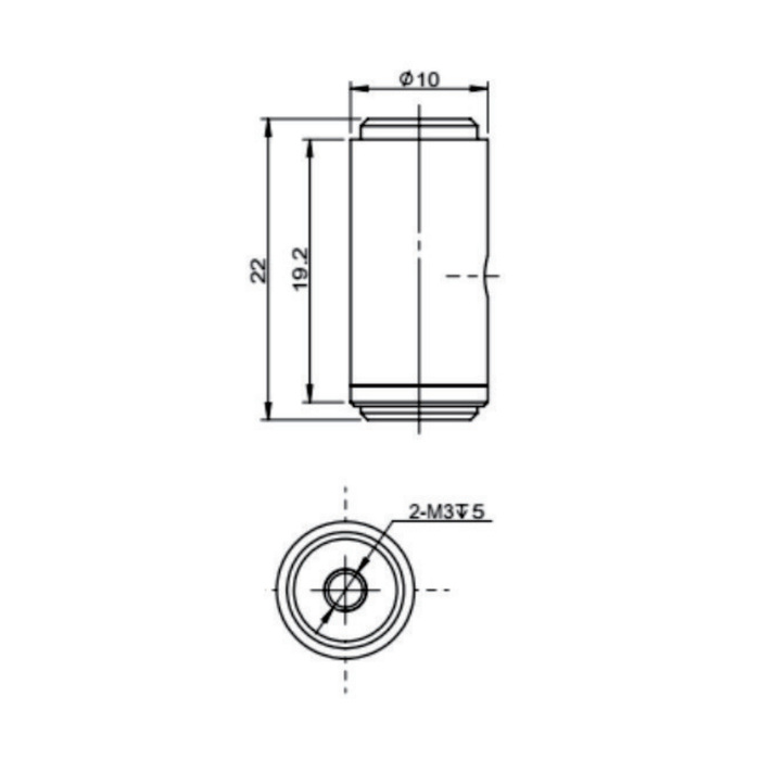
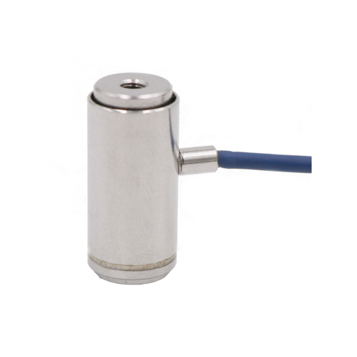
METRAVON MV-LC0229 is a miniature axial force sensor with 10, 20, 30, 50 and 100 N capacity options. Its cylindrical body has threaded connections at both ends for tension or compression along the sensor axis. It is not a shear pin intended to replace a pivot in a lifting joint.
Fit the sensor between aligned attachments
The outline is 10 mm in diameter and 22 mm overall length, with two M3 threaded holes shown at 5 mm depth. Allow additional space for the mating attachments and the side-exit cable. Check the actual screw engagement against the drawing; a screw that bottoms in a blind hole can damage the connection before the fixture is loaded.
A small axial force can be obscured by bending from a rigid misaligned fixture. Keep both attachment axes aligned and support the cable so that it does not pull on the sensing assembly. Assess installation preload and transient forces when selecting a low-range version.
Miniature axial force sensor specifications
| Characteristic | Value |
|---|---|
| Capacity options | 10, 20, 30, 50, 100 N |
| Nominal sensitivity | 2.0 mV/V, ±10% |
| Nonlinearity / hysteresis / repeatability | 0.1% FS each |
| Input / output resistance | 350 ± 30 / 350 ± 10 ohms |
| Recommended excitation | 5-12 V; maximum 15 V |
| Compensated temperature | -10 to +60 °C |
| Operating temperature | -20 to +80 °C |
| Safe overload | 150% FS |
| Cable | 2 mm diameter; 3 m length |
The sensitivity tolerance is not the measurement error after calibration. At 5 V excitation, a nominal 2 mV/V sensor produces 10 mV at rated load; the ±10% sensitivity tolerance corresponds to 9-11 mV before using the individual calibration factor. The conditioner must accommodate that range and the zero offset.
Use the force range that the test actually needs
For a spring or small-component test fixture, provide the minimum useful force, maximum force and loading direction. These are application checks, not a claim of a complete test-machine specification. If both tension and compression are measured, agree how each direction will be calibrated and how the instrument will display the sign.
For moving tests, also specify the required response time and recording rate. The static accuracy figures do not establish sensor bandwidth or system sampling performance. Confirm the measuring chain before using it to capture short peaks.
Integration questions
Q1. Can the output connect to an ordinary PLC analog input?
Not directly to a standard voltage or current input. The bridge needs a suitable excitation supply and differential millivolt input. Use a compatible bridge module or a force-measuring instrument, and specify the controller interface separately.
Q2. Is it suitable for washdown or an exposed outdoor fixture?
No protection rating or material specification is established here for that use. Provide the liquid, cleaning method and exposure conditions and obtain a documented configuration before selecting it. The operating-temperature range alone says nothing about water ingress or corrosion resistance.
Q3. What should I do if attaching the cable changes zero?
Check for cable tension and fixture misalignment before recalibrating. Repeat the reading with the cable supported in its final position. If the offset changes as the cable or attachments move, correct the mechanical disturbance rather than relying on a software zero that masks it.
Q4. What acceptance evidence should accompany a test fixture?
Use known forces at the intended working points, test the required loading directions and record the return to zero after unloading. Repeat the sequence with the final amplifier and cable arrangement. Agree the permissible error and resolution for the assembled fixture rather than treating the three 0.1% FS characteristics as one system accuracy value.
Enquire about MV-LC0229 with the force range in newtons, attachment sketch, cable route, amplifier details and required measurement speed.
