


 Chinese
 Spanish
 Russian
 Portuguese
 French
 German
 Indonesian
 Thai
 Vietnamese
 Arabic
 Italian
 Turkish
 Polish
 Japanese



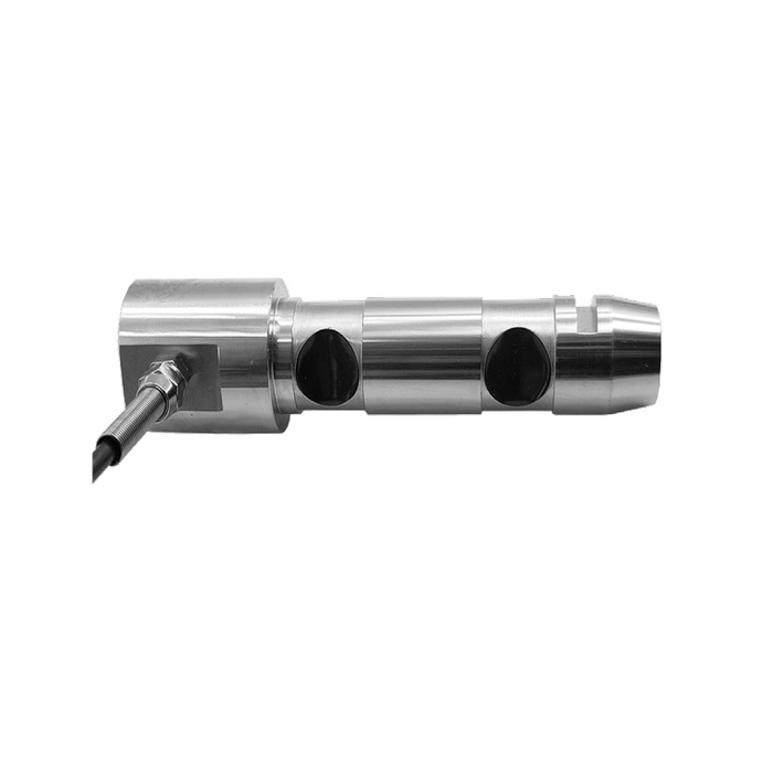
METRAVON MV-LC0228 is a load pin with 500, 1000, 1500 and 2000 kg catalogue rating options. It measures loading in a defined pin-and-support arrangement. The documented bridge has a single signal pair, so this configuration should not be specified as an independent multi-axis force measurement system.
Check the 164 mm outline against the complete joint
The drawing gives a 164 mm overall length, a 30 mm shaft diameter and a 40 mm head diameter. The shoulders and reduced sections place the sensing regions relative to the surrounding supports. Compare the entire axial layout with the joint, including retention and the cable exit. Copying only the nominal shaft diameter into a purchase order leaves the load path unresolved.
Choose the output before choosing the receiving input
The nominal bridge sensitivity is 1.5 +/-0.05 mV/V. For example, 10 V excitation gives approximately 15 mV at rated load, with the sensitivity tolerance corresponding to 14.5-15.5 mV before individual calibration. A 0-5 V output is listed as an option, but its power supply and connection details must be confirmed for that configuration. Neither option establishes an RS485 or Modbus RTU interface.
Material choice does not replace the support review
Alloy steel and stainless steel are listed alternatives. Identify the required material in the quotation, especially for wet or corrosive environments, and check the supplied configuration rather than assuming every unit is stainless steel. IP67 describes the stated ingress protection; it is not evidence of compatibility with a particular chemical cleaner or an underwater connector arrangement.
| Item | Value | Use / fit |
|---|---|---|
| Load ratings | 500, 1000, 1500, 2000 kg | Select an individual rating based on calculated pin reaction. |
| Nominal bridge output | 1.5 +/-0.05 mV/V | Do not confuse millivolts per volt with an amplified voltage signal. |
| Optional output | 0-5 V | Obtain configuration-specific supply and wiring information. |
| Nonlinearity | +/-0.05% FS | A sensor characteristic, not a complete-system accuracy guarantee. |
| Creep over 30 minutes | +/-0.03% FS | Include a sustained-load check where relevant. |
| Bridge resistance, input / output | 700 +/-10 / 700 +/-2 ohms | Match the reader to both impedance specifications. |
| Excitation, bridge version | 4-12 V DC; maximum 15 V DC | Not a confirmed supply range for the optional amplified version. |
| Working temperature | -10 to +40 deg C | Assess the actual installation environment. |
Replacement checks that affect the displayed load
Before a replacement is approved, compare the old and proposed pin geometry, loading direction, sensitivity and cable termination. After installation, check the zero and reference-load readings with the actual indicator. An unchanged connector and matching capacity do not preserve the previous calibration if sensitivity or bearing contact has changed.
MV-LC0227 has a different 120 mm outline and an optional current output, so its dimensions and electrical configuration require a separate review.
Before ordering a replacement pin
Q1. Can the model number alone establish compatibility with an existing pin?
No. Provide the old drawing or measured axial layout, not just the pin diameter and maximum load. The support positions, cable access and retention all need comparison before the new unit is accepted mechanically.
Q2. What must be stated to receive a usable quotation?
Include the selected rating, joint drawing, material option, output type and receiving instrument. For the 0-5 V option, ask for supply voltage, pinout and output scaling in the quotation documents. Add the required calibration record and commissioning method.
