


 Chinese
 Spanish
 Russian
 Portuguese
 French
 German
 Indonesian
 Thai
 Vietnamese
 Arabic
 Italian
 Turkish
 Polish
 Japanese



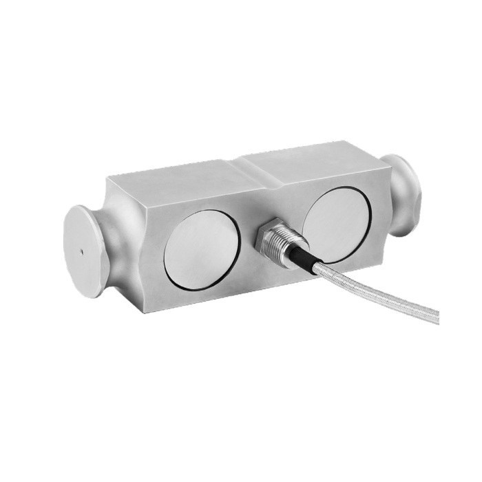
METRAVON MV-LC0209 is a double-ended shear beam load cell specified at 50 or 60 klb for truck-scale and weighing-module applications. Its drawing gives a 209.55 mm overall length and shaped bearing features. A common capacity or a similar outline elsewhere in a scale catalogue does not identify the same mating contacts.
Double-ended shear beam load cell replacement starts at the contacts
Compare the end profiles, central loading contact, restraints and cable-entry position with the existing installation. The outline includes R12.7 bearing-profile callouts and a 1/2-14 NPT cable entry. Check the mating bearing contacts and the cable-entry hardware against the selected assembly drawing. Do not approve a replacement by overall length alone.
Check the scale mechanics before removing a suspect sensor
Investigate debris, seized or worn contacts, binding restraints and damage to cable entries or terminal boxes. A deck that bears on an external object can change indication without a failed bridge. Record which loading positions produce the problem and whether zero returns after unloading. This information is more useful for replacement selection than a single unexplained weight difference.
Confirm the 50 or 60 klb rating and the indicator input
The two rating options share the published 3.0 +/-0.003 mV/V output specification. They are not made equivalent by assigning the same display range. Check the mechanical rating and calibrate the individual installed unit. The bridge requires 4-12 V DC excitation, maximum 15 V DC; verify the reader's input range if the previous installation used another nominal sensitivity.
| Item | Value | Use / fit |
|---|---|---|
| Rated options | 50, 60 klb | Confirm the actual selected rating and maximum support reaction. |
| Overall length | 209.55 mm | Compare the complete profile and restraints, not length alone. |
| Bridge resistance, input / output | 700 +/-10 / 702 +/-2 ohms | Match the connected reader and excitation source. |
| Creep over 30 minutes | +/-0.02% FS | Use a defined loading duration during verification. |
| Working temperature | -30 to +70 deg C | Assess temperature and corrosion exposure at the installation. |
| Safe / destructive entries | 150 / 300% FS | Not evidence of a permissible vehicle impact or dynamic range. |
| Construction | Alloy steel; IP67 | Does not seal a separate cable splice or junction box. |
Complete the cable route before the load-position checks
A four-core 16 m cable is listed for the 10-75 klb group, which covers both options on this page. Protect its final route and any terminal enclosure against the actual exposure. After the bearing assembly is correctly seated, verify zero, reference loads and agreed deck positions, including unloading. Retain the sensor identification and new settings with the test results.
MV-LC0207 also includes 50 and 60 klb options but has different dimensional groups; a capacity match does not settle mounting compatibility.
Truck-scale maintenance questions
Q1. Does matching the old 50 klb nameplate settle compatibility?
It settles only one item. Supply the old sensor outline, load-introduction hardware and retention details, plus cable and reader information. Bearing mismatch can remain even where capacity and nominal sensitivity agree.
Q2. Can this be used for moving-vehicle weighing without further review?
The available information does not establish a dynamic weighing performance or vehicle-speed limit. Define the actual operating mode and obtain system-level suitability and acceptance requirements before using static reference-load results to support a different duty.
Q3. When does calibration need to be repeated?
After a sensor or a load-introduction part is replaced, verify the installed measurement chain before returning the scale to service. Also recheck when cable modifications or instrument changes alter the measurement conditions; retaining the old settings is not a test.
