


 Chinese
 Spanish
 Russian
 Portuguese
 French
 German
 Indonesian
 Thai
 Vietnamese
 Arabic
 Italian
 Turkish
 Polish
 Japanese



METRAVON MV-LC0207 is a double-ended shear beam load cell with 25, 40, 50, 60, 75, 100 and 125 klb options. For an existing truck scale, the critical comparison includes the shaped bearing surfaces and support positions, not just the rated load. Different capacity groups use different outlines and cable-entry details.
Resolve the 50 klb configuration before quoting a replacement
The table shows a 25-50 klb group marked SE, a 50-75 klb group and a 100-125 klb group. Overall lengths are 209.6, 292.1 and 368.3 mm respectively. Because 50 klb appears in two groups, specifying that rating alone cannot identify the mounting. Obtain the exact configuration drawing and compare the complete geometry before retaining the old supports.
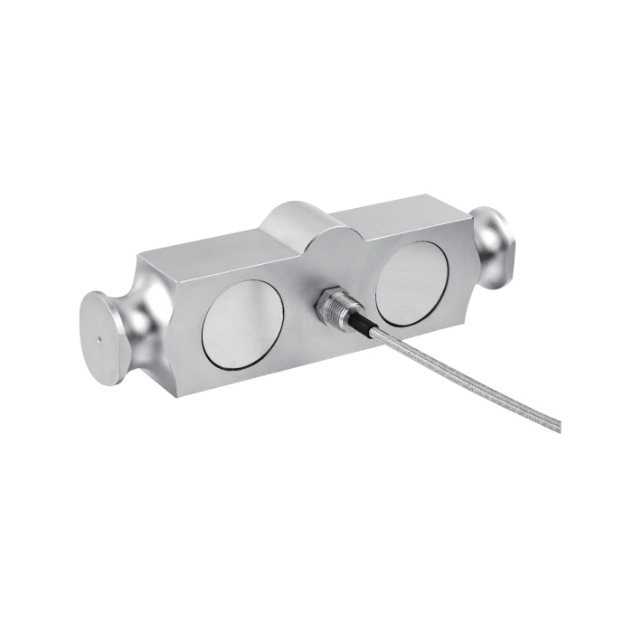
Double-ended shear beam load cell contacts must match the supports
Review the end bearing features, central contact, retention and available movement as one assembly. A worn contact or a restraint that binds under load can change the force transmitted to the sensing element. Inspect those parts when investigating unstable zero or load-position errors. Do not expect a new sensor to correct a damaged or incorrectly assembled load-introduction mechanism.
| Item | Value | Use / fit |
|---|---|---|
| Rating options | 25, 40, 50, 60, 75, 100, 125 klb | Identify the selected geometry as well as capacity. |
| Outline groups | SE; 50-75 klb; 100-125 klb | 50 klb overlaps two groups and requires drawing confirmation. |
| Input / output resistance | 700 +/-10 / 702 +/-2 ohms | Confirm the reader supports the connected bridge arrangement. |
| Creep over 30 minutes | +/-0.02% FS | Consider load-hold conditions during verification. |
| Working temperature | -30 to +70 deg C | Check actual exposure near the mounting and cable entry. |
| Safe / destructive entries | 150 / 300% FS | Not a routine measuring range or impact specification. |
| Construction | Alloy steel; IP67 | Do not infer stainless steel or chemical-cleaning compatibility. |
Check cable-entry hardware as well as signal wiring
The dimensional table uses a 1/4-18 NPT cable-entry detail for the SE group and 1/2-14 NPT for the larger groups. Confirm the matching cable gland and its clearance against the selected drawing. The standard 16 m four-core cable note covers 10-75 klb, leaving the 100 and 125 klb cable configuration to be confirmed on the quotation.
Re-establish the measuring channel after installation
The bridge is rated at 3.0 +/-0.003 mV/V and requires 4-12 V DC excitation, with a 15 V DC maximum. Check the existing indicator input before reusing its settings. After the final cable connection and mechanical seating, verify zero, reference loads and agreed deck positions. Keep the replacement calibration and individual sensor record rather than treating the old span setting as proof of compatibility.
For a 50 or 60 klb installation, MV-LC0209 is another geometry to assess, not a capacity-based drop-in replacement.
Replacement configuration questions
Q1. Can the old mating blocks be retained?
Only after checking their dimensions, condition and contact with the selected version. Equal capacity does not show that the bearing profile, support span or cable access remains correct. Include photographs and the assembly drawing in the replacement review.
Q2. Does a 3 mV/V match preserve the calibration automatically?
No. The supplied unit, support contact and cable conditions still require verification. Use the previous settings only as an initial reference, then check the installed channel and the full scale with an agreed loading procedure.
Q3. What if documentation only gives the old sensor capacity?
Obtain the missing dimensions before committing to a replacement. Measure or retrieve the full mounting arrangement under an appropriate maintenance procedure, and provide the reader details. A capacity-only enquiry cannot settle the overlapping 50 klb configuration.
