


 Chinese
 Spanish
 Russian
 Portuguese
 French
 German
 Indonesian
 Thai
 Vietnamese
 Arabic
 Italian
 Turkish
 Polish
 Japanese



METRAVON MV-LC0206 is a double-ended shear beam load cell for truck-scale and weighing-module assemblies. Listed capacities are 5, 10, 20, 25, 40, 50, 60, 75 and 100 klb. Here klb denotes thousands of pounds, not metric tonnes. Keep the capacity unit explicit when comparing an existing installation or requesting replacement hardware.
Capacity alone does not identify the mounting envelope
The dimensional table separates a 20-40 klb group from a 50-125 klb group. Their overall lengths are 209.6 mm and 260.4 mm respectively, with different body and support dimensions. The 125 klb group label is not an added capacity offer; the listed options on this page stop at 100 klb. No dimensional row is provided for the listed 5 or 10 klb versions, so obtain their drawings rather than extrapolating the smallest available outline.
| Item | Value | Use / fit |
|---|---|---|
| Published capacity choices | 5, 10, 20, 25, 40, 50, 60, 75, 100 klb | Specify one rating with its selected drawing. |
| Rated sensitivity | 3.0 +/-0.003 mV/V | A scale-factor tolerance, not finished-scale uncertainty. |
| Bridge input / output resistance | 700 +/-10 / 702 +/-2 ohms | Check excitation loading and the measuring channel. |
| Excitation | 4-12 V DC; maximum 15 V DC | Unamplified bridge output requires a suitable reader. |
| Creep, 30 minutes | +/-0.02% FS | Define the required loaded hold during acceptance. |
| Working temperature | -30 to +70 deg C | Assess the installation exposure and temperature changes. |
| Material / protection | Alloy steel / IP67 | Review cable joints and corrosion exposure separately. |
Show the complete double-ended shear beam load cell assembly
Provide the end support arrangement, loading contact and restraints together with the deck or module drawing. The shaped bearing regions must match the mating hardware and intended load path. Assess the maximum reaction at an individual measuring point, including off-centre vehicle placement and the loading conditions. Dividing total scale load equally by the number of sensors does not establish the highest reaction each will experience.
Use a 3 mV/V bridge input and the selected cable
At 10 V excitation, nominal output at rated load is about 30 mV before the sensitivity tolerance and initial offset. Verify indicator input headroom and calibration adjustment, especially when replacing a 2 mV/V device. The four-core 16 m cable note covers 10-75 klb; it does not confirm the cable supplied with 5 or 100 klb versions. Specify the actual rating and cable route in the enquiry.
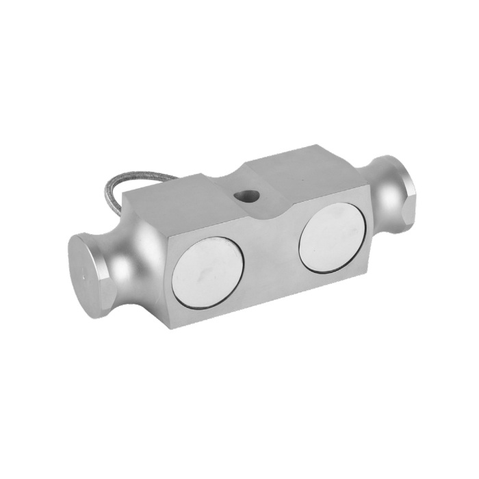
Accept the sensor within the assembled scale
After installation, check zero and controlled reference-load results with the bearing hardware in its final state. Include the agreed positions on the deck and unload checks to identify restraint or seating problems. Retain individual sensor identification, indicator settings and test conditions. Any required scale approval and acceptance procedure must address the complete instrument; a sensor classification is not that approval.
MV-LC0207 has its own bearing profiles and dimensional groups; compare its drawing only as a separate mounting option.
Drawing and capacity questions
Q1. Can the 5 klb version use the 20-40 klb mounting drawing?
That is not established by the available dimensional table. Request the selected 5 klb drawing and compare all bearing and retention features before making adapters. A nominally smaller rating does not prove a smaller or identical body.
Q2. What should be sent for a replacement quotation?
Provide the old sensor and mounting drawings, rated capacity with units, support locations, cable route and indicator model. Include the maximum expected reaction and the scale verification requirements so mechanical fit and electrical setup can be reviewed together.
