


 Chinese
 Spanish
 Russian
 Portuguese
 French
 German
 Indonesian
 Thai
 Vietnamese
 Arabic
 Italian
 Turkish
 Polish
 Japanese



METRAVON MV-LC0205 is a double-ended shear beam load cell with end fixing holes and a shaped central loading region. Ratings are 5, 10, 20, 25, 30, 40, 50, 60, 75 and 100 klb. Its dimensional groups change both the body section and mounting arrangement, so a capacity increase cannot be treated as an indicator adjustment alone.
Use the selected body length and fixing span together
The table gives overall length A = 206.2 mm and fixing-centre span D = 174.8 mm for both 5-10 klb and 20-25 klb, but their body heights differ. For 30-75 klb, A and D are 260.4 and 215.9 mm. At 100 klb they become 285.8 and 241.3 mm. Compare every relevant contact and hole dimension, not only the two lengths, before retaining the supports.
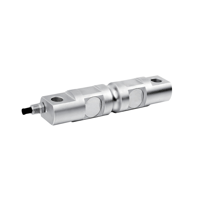
Double-ended shear beam load cell mounting needs controlled contacts
The loading feature, end-hole supports and restraints must form the intended mechanical arrangement. Check the selected drawing for fasteners, bearing surfaces and permitted movement rather than choosing parts from a photograph. Side contact with the surrounding frame can alter how load reaches the sensor. For an existing scale, inspect worn contacts and binding restraints before attributing an unstable result to the electrical bridge.
| Item | Value | Use / fit |
|---|---|---|
| Capacity options | 5, 10, 20, 25, 30, 40, 50, 60, 75, 100 klb | Specify one rating and its exact drawing group. |
| 5-10 vs 20-25 klb bodies | Same A and D; different height | A matching fixing span is not a complete fit check. |
| Output resistance | 702 +/-2 ohms | Confirm the measuring input and individual calibration. |
| Excitation range | 4-12 V DC; maximum 15 V DC | The raw bridge does not provide a direct PLC current signal. |
| Cable qualification | 16 m note covers 10-100 klb | Obtain the cable details for a 5 klb order. |
| Working temperature | -30 to +70 deg C | Review actual sensor exposure and cable protection. |
| Construction / ingress | Alloy steel / IP67 | No stainless-steel or chemical-cleaning capability is established. |
The 5 klb cable needs confirmation
The standard cable note states four-core, 16 m for 10-100 klb. It does not identify the cable delivered with the listed 5 klb option. Confirm that configuration and the route to the junction box or reader before ordering. Complete any agreed extension or termination work before establishing the final zero and span, and protect those external connections for the environment.
Check low and high working loads with the installed reader
Nominal sensitivity is 3.0 +/-0.003 mV/V and the bridge input resistance is 700 +/-10 ohms. Select the reader for the signal and connected bridge arrangement, not for the capacity label alone. During acceptance, record representative loads, repeated loading, unload return and relevant load positions. The 30-minute creep entry is +/-0.02% FS; define the hold test from the actual process duty.
For an alternative bearing arrangement, review MV-LC0204 with its own dimensional groups and supports rather than transferring the existing fixing layout.
Mounting and capacity questions
Q1. Will a larger rating automatically improve overload protection?
Not without reviewing the mounting and required measurement performance. Different groups can have different dimensions, and the same small load produces a smaller fraction of rated output at a higher capacity. Evaluate the peak reaction and useful low-load result before changing the selection.
Q2. Can a 20 klb unit fit supports made for the 10 klb version?
Not on fixing span alone. Both groups list A = 206.2 mm and D = 174.8 mm, but body height G is 43.2 mm for 5-10 klb and 49.5 mm for 20-25 klb. Check the central load contact, supporting surfaces and clearance against the selected drawing before retaining the existing supports.
Q3. What makes a replacement enquiry complete?
Provide the old sensor outline, end-hole and contact geometry, rated load with units, support reactions, cable route and reader model. Include the acceptance procedure so the proposed replacement can be checked in the actual weighing assembly.
