


 Chinese
 Spanish
 Russian
 Portuguese
 French
 German
 Indonesian
 Thai
 Vietnamese
 Arabic
 Italian
 Turkish
 Polish
 Japanese



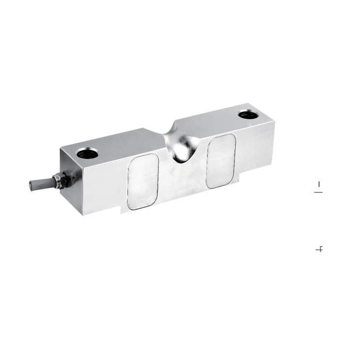
METRAVON MV-LC0204 is a double-ended shear beam load cell for truck scales and weighing-module assemblies. Available ratings are 10, 20, 25, 40, 50, 60 and 75 klb, where klb means thousands of pounds. The selected capacity must remain linked to its complete dimensional configuration, especially at 50 klb.
At 50 klb, equal length does not establish equal geometry
The table includes a 40-50 klb SE row and a 50-75 klb row. Both give overall length E = 260.4 mm, but other section and contact dimensions differ. Their cable-entry details are also different: 1/4-18 NPT for the SE row and 1/2-14 NPT for the 50-75 klb row. Request the exact configuration drawing before approving mating parts or an old mounting base.
| Item | Value | Use / fit |
|---|---|---|
| Rated options | 10, 20, 25, 40, 50, 60, 75 klb | Keep capacity units and exact configuration on the order. |
| 10-25 klb overall length E | 196.9 mm | Other contact and fixing dimensions require the full drawing. |
| 50 klb configuration | SE or 50-75 klb dimensional row | Same E length does not resolve the variant. |
| Rated sensitivity | 3.0 +/-0.003 mV/V | Not a statement of complete-scale accuracy. |
| Excitation | 4-12 V DC; maximum 15 V DC | Requires a bridge reader or conditioner. |
| Creep over 30 minutes | +/-0.02% FS | Set the loaded-hold requirement for the actual weighing task. |
| Working temperature / material | -30 to +70 deg C / alloy steel | IP67 does not protect an unsealed cable splice. |
Review the double-ended shear beam load cell assembly as a whole
The end supports, central contact and restraints determine how force reaches the beam. Check their geometry, condition and available movement using the selected drawing. Assess the largest reaction at an individual measuring point under the relevant deck positions. A scale total divided by sensor count is only an average and does not establish the highest individual load.
Set up the reader for a 3 mV/V bridge
Rated output is 3.0 +/-0.003 mV/V, with 700 +/-10 ohms input resistance and 702 +/-2 ohms output resistance. Confirm the reader's excitation loading, signal range and calibration adjustment. In particular, do not transfer a 2 mV/V scale factor unchanged. A four-core 16 m cable is listed for the published 10-75 klb range; finish its final route and termination before calibration.
Verify after the bearing contacts are seated
Record zero, reference-load response and unload return with the complete mounting in place. Repeat the agreed deck positions to identify contact or restraint problems before adjusting instrument filtering. The safe-overload figure of 150% FS and destructive-load figure of 300% FS do not establish a permitted vehicle impact or an extension of the normal weighing range.
MV-LC0205 uses a different body and end-hole mounting arrangement; compare it only as a separately reviewed mechanical option.
Configuration and replacement decisions
Q1. Can a 75 klb version use the existing 50 klb mounting parts?
Check which 50 klb configuration is installed first. A 50 klb SE unit and a 50-75 klb unit share the listed overall length but differ in other contact dimensions and cable-entry details. Compare the actual mating hardware with the selected 75 klb drawing before retaining any part of the mounting.
Q2. What should be provided when replacing a 50 klb unit?
Send the old drawing and contact hardware details, not only the nameplate rating. Identify the SE or other configuration where known, include cable access and reader details, and verify the selected replacement against the complete assembly before ordering.
