


 Chinese
 Spanish
 Russian
 Portuguese
 French
 German
 Indonesian
 Thai
 Vietnamese
 Arabic
 Italian
 Turkish
 Polish
 Japanese



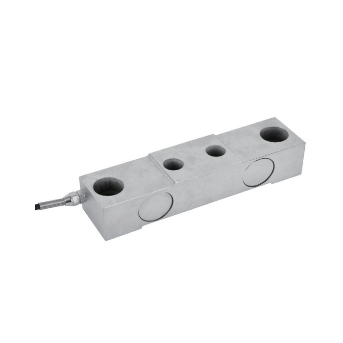
METRAVON MV-LC0203 is a beam load cell listed for vessel scales and crane-rail weighing, with 10, 20, 30 and 40 t options. Its bare-beam geometry differs from the spherical-contact assemblies of MV-LC0201 and MV-LC0202. The vessel support or rail structure must provide the intended load path; the sensor alone does not define a complete weighing module.
Begin with vessel or rail reactions, not a generic scale total
For a vessel, include the empty structure, maximum contents and forces introduced by connected equipment or piping. For a crane-rail proposal, identify the actual measurement points and the load positions used to determine their reactions. Do not assume equal loading at every point or treat a listed application as an impact rating. Describe whether the measured load is settled or changing during the reading.
Beam load cell mounting needs an assembly drawing
The outline shows a 240 mm body length, 60 mm width and 50 mm height. Submit the supporting members, load contacts, restraints and fastener engagement for review against the full drawing. Preserve clearance where the sensing structure must deform. A rigid connection to neighbouring equipment can transmit force into or around the measuring point, so the mechanical review must include more than the sensor outline.
| Item | Value | Use / fit |
|---|---|---|
| Listed capacities | 10, 20, 30, 40 t | Confirm the selected rating and its installation drawing. |
| Nominal output | 2.0 +/-0.002 mV/V | Verify the installed channel rather than using nominal gain as acceptance. |
| Excitation | 4-12 V DC; maximum 15 V DC | The sensor is not a direct industrial current or serial-output device. |
| Creep over 30 minutes | +/-0.02% FS | Agree the actual duration and acceptable indication change. |
| Safe / destructive entries | 150 / 200% FS | Different from adjacent assemblies; not a routine operating allowance. |
| Working temperature | -30 to +70 deg C | Assess exposure at the sensor and the cable. |
| Construction / protection | Alloy steel / IP67 | Protect the final cable joints and terminal enclosure separately. |
Keep the sensor range and the instrument setup distinct
The listed bridge output is 2.0 +/-0.002 mV/V, with 700 +/-10 ohms input resistance and 702 +/-2 ohms output resistance. The sheet gives +/-0.02% FS total error, but that does not define the installed vessel or rail-scale result. Use a suitable bridge reader and establish its scale factor with reference loading in the accepted mechanical arrangement.
Arrange access for repeatable verification
The listed four-core cable is 16 m for the 10-40 t options. Plan its protection and the reference-loading access before the supports are enclosed or difficult to reach. Record zero, loaded points, unloading and any relevant load-position checks. If the load remains applied, include the required hold duration rather than assuming that a brief span check covers the operating cycle.
Vessel and rail installation questions
Q1. Can the vessel weighing system be verified at only one loading point?
The test must represent the complete supported structure and its required weighing task. Define the loading method and observe whether piping, restraints or supports change the force transfer. A single local check does not establish every load position or the weighing behaviour of the assembled vessel.
Q2. Can it weigh while the crane is moving?
The available data does not specify weighing accuracy during travel, a travel-speed limit or impact performance. Describe the intended operating cycle and obtain an installation-specific review before selecting this sensor for readings taken while loads are changing or moving.
Q3. What should I send for a vessel or crane-rail weighing quotation?
Send the support layout, selected capacity, maximum and minimum relevant reactions, connected equipment, operating temperatures and reader details. Include how reference loading will be applied, so the quoted sensor, mounting requirements and calibration scope address the real installation.
