


 Chinese
 Spanish
 Russian
 Portuguese
 French
 German
 Indonesian
 Thai
 Vietnamese
 Arabic
 Italian
 Turkish
 Polish
 Japanese



METRAVON MV-LC0208 is a double-ended shear beam load cell offered in discrete ratings from 1 klb to 125 klb. The broad list does not describe one adjustable sensor or one body size. Its end-hole mounting and central loading region need a capacity-specific base and load-introduction arrangement.
Choose the mounting span from the selected capacity row
The drawing labels overall length as C and the end-hole centre span as D. For 1-5 klb, those values are 190.5 and 158.8 mm; for 10-25 klb, 222.3 and 190.5 mm. The 50 and 75 klb rows use 342.9 and 292.1 mm, while 100-125 klb uses 469.9 and 381.0 mm. Other details also change, so these two dimensions are not a complete replacement drawing.
| Item | Value | Use / fit |
|---|---|---|
| Capacity options | 1, 2, 2.5, 3, 5, 10, 25, 35, 50, 75, 100, 125 klb | Choose one listed rating; retain its unit and drawing identity. |
| Nominal sensitivity | 3.0 +/-0.003 mV/V | Individual scale setup and verification are still required. |
| Excitation | 4-12 V DC; maximum 15 V DC | Check the supply load for the actual number of connected bridges. |
| Creep, 30 minutes | +/-0.02% FS | Set a hold-test requirement from the weighing task. |
| Temperature effects, zero / sensitivity | Each +/-0.02% FS per 10 deg C | Assess environmental changes at the installed sensor. |
| Working temperature | -30 to +70 deg C | Not an accuracy guarantee for the complete installation. |
| Material / ingress | Alloy steel / IP67 | Review cable termination protection separately. |
Review the complete double-ended shear beam load cell load path
The supports, fasteners and loading contact determine how force enters the beam. Obtain the actual drawing for hole sizes, body section and the load-contact features; do not create a new mounting by scaling a photograph. State the required support reactions and restraint arrangement. For a multi-sensor scale, consider the most demanding load position rather than assuming every sensor always carries an equal fraction.
The measuring signal is not a control-system output
This version has a 3.0 +/-0.003 mV/V bridge output, 700 +/-10 ohms input resistance and 702 +/-2 ohms output resistance. A suitable indicator or acquisition module supplies excitation and reads the differential signal. If the project needs PLC integration, specify the separate reader interface and scaling; a raw bridge does not establish direct 4-20 mA or RS485 capability.
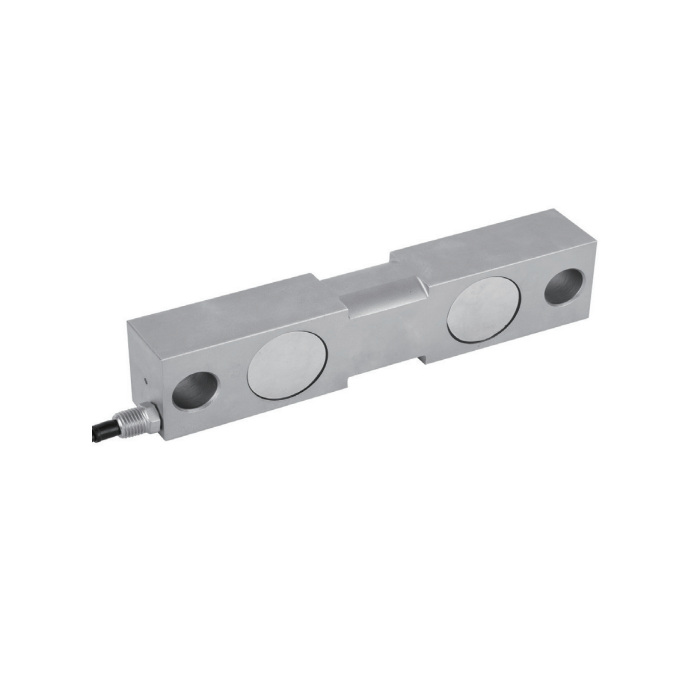
Specify cable and verification with the capacity
The 16 m four-core cable note covers 10-75 klb, not all listed ratings. Confirm the supplied cable for 1-5 klb and 100-125 klb before deciding where the junction box or indicator will sit. Commission after the final mounting and cable route are complete, recording zero, reference-load response and repeated unloading. Agree any calibration-document requirements when requesting the quotation.
Compare MV-LC0206 where its shaped end-bearing arrangement is more relevant than an end-hole mount, but assess the complete assembly independently.
Mounting and acquisition decisions
Q1. Can a larger capacity use the existing end-hole spacing?
Not in general. The table changes the overall length and fixing span across capacity groups, and body details change as well. Compare the selected row and complete drawing against the existing mount before approving a capacity increase.
Q2. What should be included in a weighing-module enquiry?
Supply the structure drawing, capacity and maximum individual support reaction, load direction, restraints and expected movement. Add the reader model, cable route and acceptance procedure so the mechanical assembly and signal chain can be specified together.
