


 Chinese
 Spanish
 Russian
 Portuguese
 French
 German
 Indonesian
 Thai
 Vietnamese
 Arabic
 Italian
 Turkish
 Polish
 Japanese



METRAVON MV-LC0195 is a 500 kg clevis-end tension load cell for hanging scales and tensile test fixtures. Both ends use forked connections rather than the threaded fittings of an S-type sensor. The electrical and environmental specifications also differ: nominal output is 1.5 mV/V, ingress protection is IP66 and working temperature is -10 to +40 deg C.
Fit both clevis connections without loading the sensing slots
The drawing shows a 115 mm overall length and 25 mm body width. Approve the pins, mating-part thicknesses, clearances and retention from the complete drawing, not those two outside dimensions alone. Keep the joined parts on the intended force axis and clear of the slotted central region. For a replacement, send the old joint drawing and installed length so that changes in connection geometry are identified before ordering or assembly.
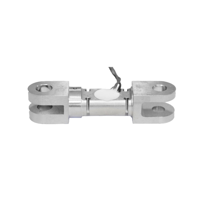
Match the 1.5 mV/V clevis-end tension load cell to its reader
The listed sensitivity is 1.5 +/-0.1 mV/V. At 10 V excitation, nominal output at rated load is about 15 mV. Input resistance is 1030 +/-20 ohms and output resistance is 1001 +/-3 ohms. A previous 2 mV/V sensor calibration is therefore not a valid substitute for setting up this sensor. Confirm the bridge input, supplied wiring and cable length, then calibrate the installed channel over the force interval needed by the fixture.
Keep IP66 and the temperature limit on the order
Alloy steel and IP66 are specified; there is no IP67 or stainless-steel specification for this model in the available data. IP66 should not be treated as an immersion rating. Assess the sensor location and protect any separate junction or connector accordingly. The -10 to +40 deg C working range also needs checking where machinery or nearby processes can heat the fixture.
| Item | Value | Selection notes |
|---|---|---|
| Rated load | 500 kg | No additional capacity options are established here. |
| Overall outline | 115 mm long; 25 mm wide | Use the detailed drawing to approve each clevis interface. |
| Nominal sensitivity | 1.5 +/-0.1 mV/V | Select the input range and calibrate with the actual sensor. |
| Bridge input / output | 1030 +/-20 / 1001 +/-3 ohms | Check the reader and delivered wiring details. |
| Excitation | 4-12 V DC; maximum 15 V DC | A bridge amplifier is needed for separately required conditioned outputs. |
| Material / ingress | Alloy steel / IP66 | An immersion application requires a different documented assessment. |
| Overload figures | 150% safe / 200% ultimate | These values do not establish a permissible shock-loading cycle. |
Verify pin seating, repeat readings and unload return
Inspect the unloaded assembly for contact or cable restraint before applying reference tension. Record several loading points and repeated cycles through the working interval. Nonlinearity and 30-minute creep are each listed as +/-0.05% FS. Establish the complete fixture acceptance criteria separately; the D1 classification does not by itself prove a specified test-machine accuracy, response speed or suitability for lifting service.
For higher-force clevis-and-eye assemblies, review MV-LC0193 separately; its end geometry and 2 mV/V nominal output differ from this 500 kg model.
Fixture replacement and ordering details
Q1. Can it replace a 500 kg S-type load cell without changing the fixture?
Equal rating does not make the end connections compatible. This model has clevis ends and a different nominal output from many S-type sensors. Check both the mechanical joints and reader calibration before accepting a replacement.
Q2. What cable length will be delivered?
The available specification does not state a standard cable length. Put the required route and connection position in the enquiry and ask for delivered cable details on the offer. Do not assume the 2 m or 3 m length quoted for another sensor.
Q3. What information is needed for a test-fixture quotation?
Provide the 500 kg rating, minimum and maximum working forces, both mating connection drawings and the required installed length. Include loading cycle, temperature, reader and acceptance procedure. Identify whether pins, electronics or calibration documentation must be supplied with the sensor.
