


 Chinese
 Spanish
 Russian
 Portuguese
 French
 German
 Indonesian
 Thai
 Vietnamese
 Arabic
 Italian
 Turkish
 Polish
 Japanese



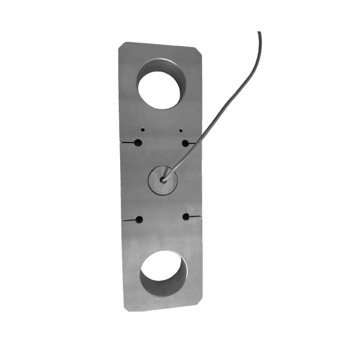
METRAVON MV-LC0194 is a tension link load cell with two eye connections and ratings of 25, 50, 100, 150, 200 and 250 klb. These are thousands-of-pounds ratings, not tonnes. Its listed working temperature is -10 to +40 deg C. Check that environmental range and the complete pin-connected assembly before selecting this model for a high-load tensile installation.
Check the site temperature before selecting the tension link load cell
The -10 to +40 deg C working range is narrower than the -30 to +70 deg C range on several adjacent models. Do not transfer the neighbouring specification to this sensor. Review the temperature at the installed link, including process heat or outdoor exposure. If conditions fall outside the listed range, seek a documented alternative rather than treating a protective cover as proof of acceptable sensor temperature.
Match pin geometry to the ordered klb rating
At 25 klb the drawing gives overall length A = 283 mm, eye-centre distance C = 183 mm and hole diameter D = 50 mm. At 250 klb these become 600, 400 and 102 mm. Intermediate ratings have their own rows. Use the complete selected dimensions to assess pins, bearing contact, adjoining clevises and movement; a larger rating is not a drop-in upgrade for smaller connection hardware.
| Item | Value | Selection notes |
|---|---|---|
| Published ratings | 25, 50, 100, 150, 200, 250 klb | Keep the capacity unit explicit in the purchase order. |
| 50 klb A / C / D | 318 / 210 / 51 mm | Overall length / eye centres / hole diameter. |
| 100 klb A / C / D | 420 / 300 / 71.4 mm | Confirm pin contact and the surrounding connection dimensions. |
| 150 klb A / C / D | 500 / 350 / 80 mm | Review the selected configuration rather than interpolating. |
| 200 klb A / C / D | 550 / 380 / 96.4 mm | Check the whole mating assembly for the higher force. |
| Excitation supply | 4-12 V DC; maximum 15 V DC | The output is a low-level bridge signal. |
| Safe / ultimate overload | 150 / 200% FS | No lifting approval follows from these overload entries. |
Specify the measuring channel and cable arrangement
Rated output is 2.0 +/-0.1 mV/V, with bridge input resistance of 385 +/-10 ohms and output resistance of 351 +/-2 ohms. The wiring diagram identifies a four-core bridge connection with a shield, but the page does not establish a standard cable length. Include the actual route and termination requirements in the quotation. Calibrate using the supplied sensitivity information and reference loading after the wiring is complete.
Separate nonlinearity from assembly acceptance
The specification gives +/-0.02% FS nonlinearity and +/-0.02% FS creep over 30 minutes. Nonlinearity is not the total error of the assembled load-measuring system. Evaluate the installed link and reader at the required force points, including repeat loading and unload return. For held tension, record the relevant hold period; for changing tension, obtain the necessary response and loading assessment rather than assuming a dynamic rating.
Temperature, accessories and signal output
Q1. Can this be selected for a -20 deg C installation?
That temperature is below the listed -10 deg C minimum. Do not approve the application from this specification alone. Provide the exposure conditions and request a version or alternative with documented temperature suitability.
Q2. Is the pin or shackle included with the tension link?
The sensor drawing does not settle the complete scope of supply. Specify any required pins, retainers, mating clevises and calibration documentation separately, and obtain a quotation that identifies what is included. Their strength and fit require an assembly-level review.
Q3. Can the bridge connect straight to an RS485 input?
RS485 is a communication interface, whereas this sensor provides an analogue bridge output. A suitable measuring instrument must excite and read the bridge before any separately specified communications output is available. Confirm the actual protocol and channel requirements with that instrument.
