


 Chinese
 Spanish
 Russian
 Portuguese
 French
 German
 Indonesian
 Thai
 Vietnamese
 Arabic
 Italian
 Turkish
 Polish
 Japanese



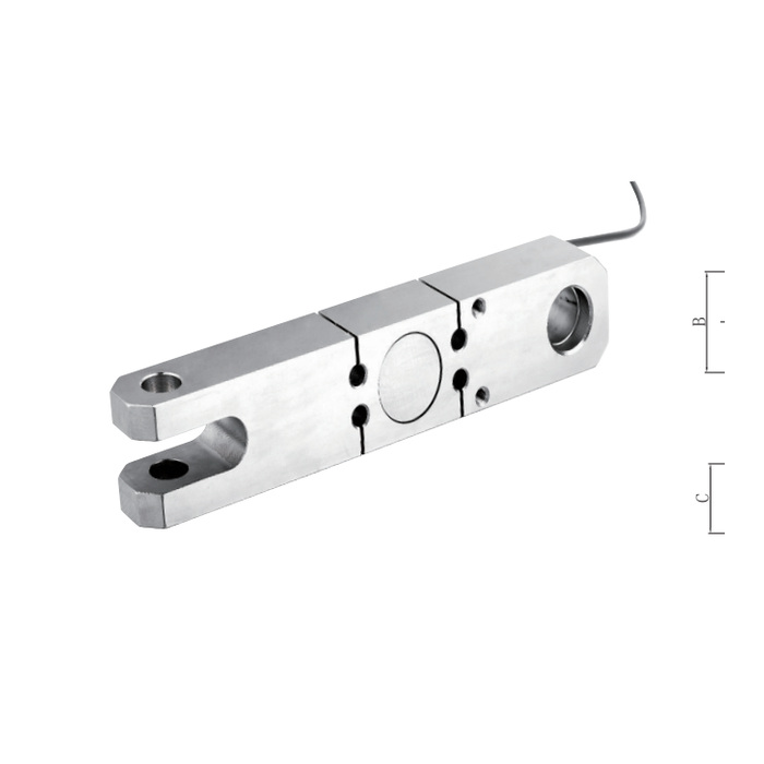
METRAVON MV-LC0193 is a clevis-and-eye tension load cell with 1, 2, 3, 5, 10 and 20 t choices. The two ends have different connection geometry, unlike a flat link with identical eyes. Before replacing a sensor or designing a tensile fixture, establish how the mating parts fit both ends and how they keep force along the intended measuring axis.
Review the clevis-and-eye tension load cell at both ends
Overall length A is 320 mm for 1-3 t, 350 mm for 5 t, 377 mm for 10 t and 460 mm for 20 t. The drawing also changes the end dimensions and body section between these groups. Send the pin diameters, mating-part thicknesses and required joint movement with the enquiry. Do not enlarge a single hole or add spacers to an old assembly without checking the resulting bearing contact and force axis.
Use the individual bridge value when setting span
Rated sensitivity is 2.0 +/-0.1 mV/V, not the much narrower sensitivity tolerance quoted for some nearby models. The input resistance is 760 +/-10 ohms and output resistance is 701 +/-2 ohms. A nominal 2 mV/V input setting can support initial setup, but the installed channel still needs reference calibration. A four-core 2 m cable is listed for the full 1-20 t group; allow for the actual connection position before installation.
Establish working-force and load-hold acceptance
Check the highest tension together with the lowest force the project needs to measure. Include the weight of connected fixtures where it reaches the sensor and describe any repeated or changing load cycle. The 30-minute creep entry is +/-0.02% FS. Agree how a held force, repeated cycles and unloading will be checked with the chosen reader, rather than treating a single loaded display value as a complete acceptance test.
| Item | Value | Selection notes |
|---|---|---|
| Rating options | 1, 2, 3, 5, 10, 20 t | The attachment arrangement must suit the selected version. |
| A, 1-3 t / 5 t | 320 / 350 mm | Check the full clevis and eye dimensions, not length alone. |
| A, 10 t / 20 t | 377 / 460 mm | Use the confirmed selected drawing for the mating hardware. |
| Signal sensitivity | 2.0 +/-0.1 mV/V | Use calibration data for the actual sensor and channel. |
| Standard cable | Four-core, 2 m | Agree extension and termination before commissioning. |
| Excitation | 4-12 V DC; maximum 15 V DC | Confirm the bridge input and required power supply. |
| Temperature / overload | -30 to +70 deg C; 150 / 200% FS | Safe / ultimate overload does not specify a fatigue rating. |
Protect joint movement and the electrical connection
Keep the sensing slots clear of adjacent hardware and provide cable support that does not pull on the measuring element. Verify the ordered alloy-steel or stainless-steel version and the protection of any external connector. IP67 is listed for the sensor, but it does not establish chemical compatibility, a permissible side load or a service life for a moving joint.
Pin fit and installed measurement
Q1. Can I retain the old pin if it enters the new clevis?
Physical insertion is only one check. The mating widths, contact length, clearances, retention and load direction must also match the reviewed assembly. Provide the old pin and joint drawings before accepting reused hardware.
Q2. Does the C3 entry establish the complete test-rig accuracy?
The published sensor classification does not include fixture friction, bending, reader errors or the reference-loading method. Define the required installed measurement result and verify it with the actual end connections and electronics.
