


 Chinese
 Spanish
 Russian
 Portuguese
 French
 German
 Indonesian
 Thai
 Vietnamese
 Arabic
 Italian
 Turkish
 Polish
 Japanese



METRAVON MV-LC0192 is a tension load cell with one threaded end and one eye connection, offered at 1, 1.5, 2, 3, 5, 7.5, 10 and 15 t. It suits a tensile assembly only when both mating connections can transmit the intended force without binding. The thread, eye dimensions and body envelope change with rating, so the complete linkage drawing is needed for selection.
Treat the thread and eye as two different interfaces
For the 1-5 t group, the drawing gives M18 x 1.5 and dimensions A/B/C = 76/32/117 mm. At 7.5 t the thread is M24 x 1.5 and A/B/C = 88/32/125 mm. The 10-15 t group uses M30 x 2 and 100/50/167 mm. Eye dimensions D1/D2 change from 23.5/27 mm in the lower groups to 30/37 mm at 10-15 t. Use the complete eye profile to approve the mating pin rather than selecting it from one diameter alone.
| Item | Value | Selection notes |
|---|---|---|
| Discrete ratings | 1, 1.5, 2, 3, 5, 7.5, 10, 15 t | Select the force rating and its matching connection group. |
| 1-5 t thread | M18 x 1.5 | Check engagement and the adjoining threaded component. |
| 7.5 t thread | M24 x 1.5 | The lower-group fitting is not interchangeable. |
| 10-15 t thread | M30 x 2 | Verify the larger eye and body at the same time. |
| Total error / creep | +/-0.02% FS / +/-0.02% FS | The creep entry is for 30 minutes, not instantaneous resolution. |
| Excitation / temperature | 4-12 V DC / -30 to +70 deg C | Maximum excitation is 15 V DC. |
| Overload entries | 150% safe / 200% ultimate | Do not infer lifting-system approval or cyclic-load life. |
Plan cable reach before closing the suspended assembly
The four-core cable note gives 3 m for 1-5 t, 6 m for 7.5 t and 10 m for 10 t. It does not state the standard length for the listed 15 t rating. Obtain that detail in the 15 t offer instead of copying the 10 t entry. Route the cable independently of the load-bearing connections and leave access for inspection of both the cable exit and terminations.
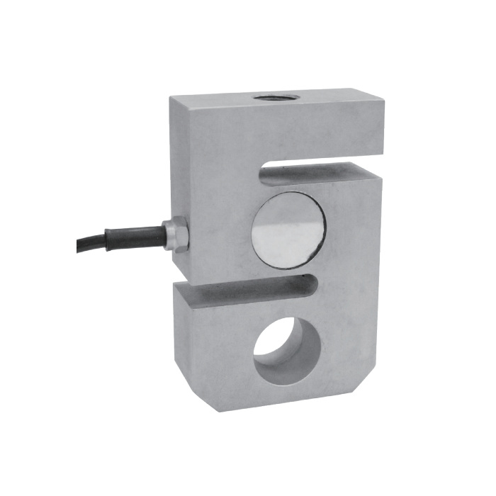
Connect and calibrate the tension load cell in its final linkage
Rated output is 2.0 +/-0.002 mV/V, with 385 +/-10 ohms input resistance and 350 +/-2 ohms output resistance. Confirm the reader accepts that bridge and its excitation requirements. Seat the threaded and pinned connections before setting zero, then apply agreed reference loads through the complete assembly. Check increasing and decreasing loads if friction or rotation at the eye could affect the indication.
Where a clevis-and-eye arrangement is needed instead, compare MV-LC0193 against a revised assembly drawing; it is not a thread-compatible replacement.
Eye connection and cable selection
Q1. Is the 15 t cable necessarily 10 m long?
The listed cable note assigns 10 m to 10 t, not to the whole 10-15 t dimensional group. Obtain the delivered 15 t length and wiring details before placing the order or positioning the indicator.
Q2. Can a binding eye be corrected with indicator filtering?
Filtering changes the displayed response, not the load transfer through a tight or misaligned connection. Inspect pin fit, surrounding clearance and the freedom needed by the designed linkage. Correct the mechanical cause before repeating reference-load checks.
Q3. Which parts should be included in the quotation request?
Identify whether the enquiry is for the sensor alone or for a reviewed assembly with mating components. Supply the force direction, rating, thread engagement, pin and eye drawings, installed length and reader details. State the material and cable requirements so the scope is not inferred from a photograph.
