


 Chinese
 Spanish
 Russian
 Portuguese
 French
 German
 Indonesian
 Thai
 Vietnamese
 Arabic
 Italian
 Turkish
 Polish
 Japanese



METRAVON MV-LC0196 is an S-type load cell for suspended weighing and tensile-force measurement. It is offered at 500 kg, 750 kg, 1.5 t and 3 t. Moving up to 3 t changes the body dimensions and threaded connections as well as the rated load, so an existing linkage must be checked before choosing the replacement.
The 3 t S-type load cell needs different mating threads
The 500 kg to 1.5 t group has dimensions A = 50.8 mm, B = 28 mm and C = 76.2 mm, with M12 x 1.75 connections. The 3 t drawing changes these to 76.2, 32 and 104 mm, with M20 x 1.5 connections. Compare thread pitch, engagement and the full installed length, including any rod ends. A capacity change must not leave an undersized attachment carrying the higher load.
| Item | Value | Use / fit |
|---|---|---|
| Rated choices | 500 kg, 750 kg, 1.5 t, 3 t | Select from the actual axial force, including fixtures. |
| Lower-group threads | M12 x 1.75 | Applies to 500 kg through 1.5 t. |
| 3 t threads | M20 x 1.5 | Existing M12 attachments are not a matching connection. |
| Excitation | 4-12 V DC; maximum 15 V DC | Confirm the bridge reader supply and signal range. |
| Safe / ultimate overload | 150 / 300% FS | Neither figure extends the normal measuring range. |
| Working temperature | -30 to +70 deg C | Review temperature at the sensor, not only room air. |
| Material / ingress | Steel options / IP67 | Confirm the ordered material and external connection protection. |
Keep the pull on the threaded axis
Show the complete suspended assembly, including attachments above and below the sensor and the available space for alignment. Off-axis pull can introduce bending that a capacity label does not describe. Include the hanging fixtures in the load calculation and describe starts, stops or sudden take-up of slack. The published overload entries do not establish a shock-load or fatigue rating for lifting duty.
Cable length and the bridge reader are part of the order
Standard four-core cable is 3 m for 500 kg through 1.5 t and 6 m for 3 t. Rated sensitivity is 2.0 +/-0.002 mV/V, with 385 +/-10 ohms input resistance and 350 +/-2 ohms output resistance. Use a strain-gauge bridge reader; a general voltage or current input cannot be assumed suitable. Complete the intended cable route before setting zero and span, leaving the cable free from the tensile load path.
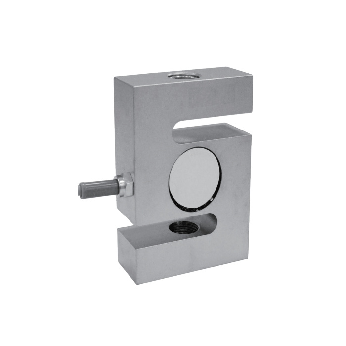
Verify the assembled linkage under reference load
After the linkage is aligned, record unloaded zero, representative reference loads and the return to zero. Repeated loading helps reveal a binding connection that a single reading can miss. Total error and 30-minute creep are each listed as +/-0.02% FS; these entries do not specify the error of the complete suspended system. Agree the required test points and allowable installed-system error before acceptance.
For lower-capacity S-type installations, compare MV-LC0197, including its different body, material groups and overload limits.
Threaded linkage and suspended-load questions
Q1. Can the 1.5 t linkage be retained for a 3 t replacement?
The sensor thread and envelope change at 3 t, so the old attachments cannot be accepted from appearance alone. Submit their drawings and load ratings along with the required installed length. Check the whole force chain before increasing the working load.
Q2. Does this sensor make a suspended assembly suitable for lifting?
A load-cell measurement specification is not a lifting-system approval. The designer must assess the load-bearing parts, retention, failure consequences and applicable requirements for the complete assembly. No lifting approval or fatigue life is established by the listed sensor overload figures.
