


 Chinese
 Spanish
 Russian
 Portuguese
 French
 German
 Indonesian
 Thai
 Vietnamese
 Arabic
 Italian
 Turkish
 Polish
 Japanese



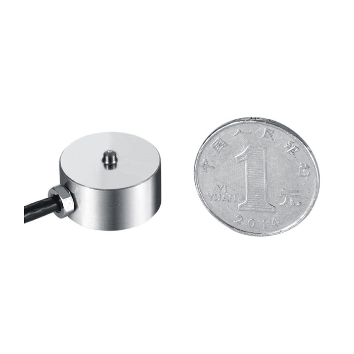
METRAVON MV-LC0116 is a miniature compression load cell with a central button above a stainless-steel diaphragm body. It is documented for assembly-force, button-feel and robotic gripping fixtures with restricted space. The 10-1000 kg family uses two contact profiles within the same 20 mm reference body diameter. That small envelope does not establish that one mating tip suits every rating.
Choose the miniature compression load cell contact profile first
At 10-200 kg the upper contact is 2.5 mm in diameter with an SR2 dome. The 300-1000 kg drawing changes it to 5 mm diameter and SR20. Both references show a 12 mm total height and a 10 mm body-height designation. Check the mating surface, the approach direction and how the pressing tool remains centred during travel. A dome radius describes geometry, not an allowed tilt angle or a universal self-aligning joint.
| Item | Value | Selection notes |
|---|---|---|
| Family range | 10-1000 kg | Confirm the selected capacity and required working-force interval. |
| 10-200 kg top contact | 2.5 mm / SR2 | Review the mating tip and centred approach. |
| 300-1000 kg top contact | 5 mm / SR20 | Do not reuse the smaller contact geometry without assessment. |
| Body diameter / total height | 20 / 12 mm | Reserve space for the mating tool and cable exit. |
| Base fixings | 3 x M3 on 15.5 mm circle | Verify engagement and base contact with the supplied drawing. |
| Cable / material | 3 m / stainless steel | Listed cable diameter is 3 mm; enclosure protection is IP66. |
Keep the button and base in one controlled force path
The underside drawing identifies three M3 fixing positions on a 15.5 mm circle. Provide the base flatness, hole arrangement and surrounding fixture clearance for assessment; agree thread engagement from the offered drawing. Introduce compression through the intended button instead of letting a cover or guide touch the upper body. If the mechanism must pull as well as push, choose an appropriate tensile connection rather than treating the base screws as proof of a tensile measuring rating.
Do not mistake sensitivity spread for a complete accuracy specification
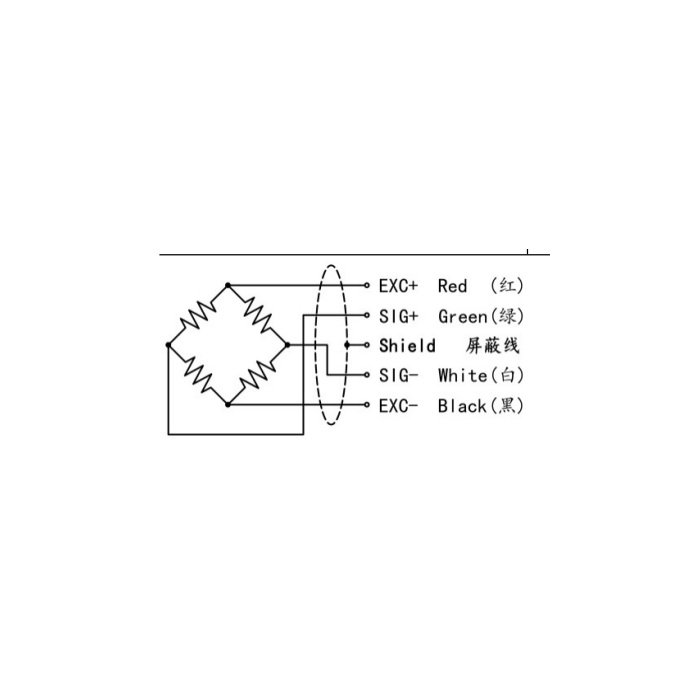
Sensitivity is 1.5 mV/V +/-10%, with 1000 +/-30 ohms input resistance and 1000 +/-5 ohms output resistance. Excitation is 5-12 V DC. Set the conditioner for the delivered sensor and calibrate through the actual contact. Nonlinearity and hysteresis are each +/-0.5% FS, with +/-0.3% FS repeatability. A nominal 1000 kg body used for a very small force still needs assessment at that working point; a matching outside diameter is not a reason to choose the largest rating.
Observe release and cable effects during repeated press cycles
Install the listed 3 m, 3 mm diameter cable with its final strain relief, then compare suitable reference forces during repeated approach and release. Check empty return after fixture movement and note whether the tool contacts differently as the part position changes. Specify any required force-versus-travel recording and cycle response with the measuring electronics. IP66 and -20 to +70 deg C are listed, but no cycle-life or dynamic-response figure is established by those entries.
Review MV-LC0114 for an opposed-stud tension and compression fixture rather than adding an unverified pulling attachment to this button sensor.
Button contact and moving-fixture checks
Q1. Will the same pressing tip suit 200 kg and 300 kg versions?
The button changes from 2.5 mm diameter with SR2 to 5 mm with SR20. Review the contact pair and approach geometry, then verify the assembled fixture. Similar body dimensions do not make those two loading surfaces equivalent.
Q2. Can the miniature body be used as a tension link?
This version is documented for compression through a top button. Its base fixing screws do not establish an axial tension interface. MV-LC0114 provides a different arrangement with opposed studs when both tensile and compressive measurement are required.
Q3. Is a bench calibration enough for a moving press fixture?
The bench result does not include the final tool contact, cable motion or guide interactions. Repeat relevant force checks with the production fixture and reader. Define the force interval and cycle conditions before accepting its use for the process.
