


 Chinese
 Spanish
 Russian
 Portuguese
 French
 German
 Indonesian
 Thai
 Vietnamese
 Arabic
 Italian
 Turkish
 Polish
 Japanese



METRAVON MV-LC0115 is a low-profile diaphragm load cell for compression-force and weighing fixtures where the loading plane must remain close to the support. Its integrated housing and flat diaphragm are documented over a 50 kg-5 t family. Use the complete fixture drawing to decide how force reaches the plate and how the body is supported; a flat top is not permission to load any part of the housing.
Protect the diaphragm within the actual machine load cycle
The specified safe-overload entry is 120% FS. Do not transfer a 150% figure from another sensor or use the overload entry as a routine measuring range. Describe approach impact, fixture preload and the peak event that can occur if a part is misplaced. Establish whether the machine needs an independently designed stop or other protection, with sufficient clearance during valid measurement. Electronic range selection alone cannot protect a diaphragm from a mechanical overload.
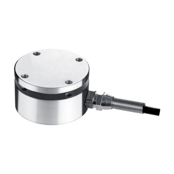
Check the low-profile diaphragm load cell plate and fixing circle
The reference outline shows a 58 mm diameter and 31 mm overall height. Four M5 positions are shown on a 42 mm circle. Review the attachment on each side, the plate support and the intended clearance around the sensing region. A mounting component that bridges a moving gap can divert force even when all holes line up. Obtain the drawing for the offered capacity before machining, and include the cable gland and tool access rather than reserving only the circular body envelope.
| Item | Value | Selection notes |
|---|---|---|
| Family range | 50 kg-5 t | Select the actual rating from the complete fixture load cycle. |
| Reference diameter / height | 58 / 31 mm | Include the load attachment and cable-gland clearance. |
| Fixing designation | 4 x M5 on 42 mm circle | Resolve plate and body attachments from the installation drawing. |
| Safe overload | 120% FS | Not a continuous working range or a recommended trip point. |
| Hysteresis / repeatability | +/-0.3% FS each | Check the installed assembly near its decision thresholds. |
| Working temperature | -20 to +70 deg C | Review process heat and the external measuring electronics. |
Agree useful force points rather than quoting a single accuracy label
Nonlinearity is +/-0.3-0.5% FS; hysteresis and repeatability are each +/-0.3% FS. Assess whether those characteristics suit the actual force interval and acceptance decision. Specify suitable reference points near the operating threshold and compare repeated loading and unloading through the production contact. For a dwell process, request the conditions behind the +/-0.1% FS creep entry: no duration is given here. A mention of medical equipment as an application is not a medical-device approval or a complete instrument accuracy statement.
Identify the bridge version and external electronics
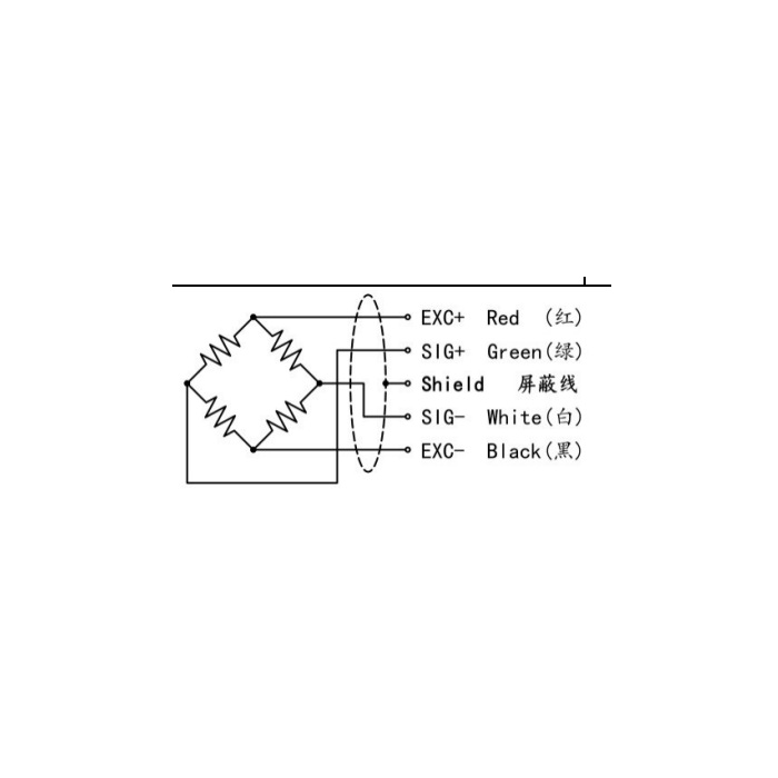
The sensitivity entry covers 1.5-2.0 mV/V with a listed +/-0.05 mV/V tolerance; confirm which nominal output is supplied. Excitation is 5-12 V DC, with 380 +/-30 ohms input resistance and 350 +/-5 ohms output resistance. Cable length is 3 m at 5 mm diameter. Match the indicator or conditioner to that raw bridge and define any required control-system output separately. IP66 and -20 to +70 deg C are listed; confirm the alloy-steel or stainless-steel version for the actual exposure.
Loading plate and overload protection
Q1. Can the top plate be covered by a larger loading platen?
Submit the proposed contact area, support geometry and force direction for review. A larger platen must not bear on unintended housing surfaces or create a changing force bypass. Confirm the assembly through reference loading rather than treating matching diameter as approval.
Q2. Can the machine overload alarm simply be set at 120%?
The safe-overload entry does not establish an alarm-response time, a protective stopping distance or an allowed operating setpoint. Assess the machine peak and the complete protective arrangement. Keep normal weighing within the approved rated range.
