


 Chinese
 Spanish
 Russian
 Portuguese
 French
 German
 Indonesian
 Thai
 Vietnamese
 Arabic
 Italian
 Turkish
 Polish
 Japanese



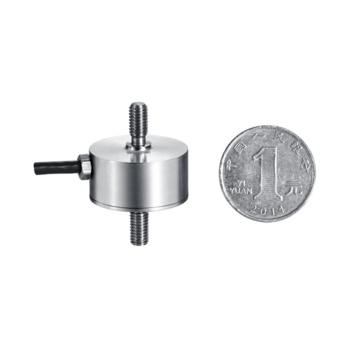
METRAVON MV-LC0114 is a miniature tension and compression load cell for space-limited assembly-force, button-feel and robotic gripping fixtures. Two axial studs carry force through a stainless-steel diaphragm body. The documented ratings are 5, 10, 20, 30, 50 and 100 kg. Select the stud size and fixture geometry alongside the force interval; the round body diameter alone does not establish a suitable fit.
Connect the miniature tension and compression load cell without winding up the body
The reference body diameter is 25.4 mm, with a 13 mm body-height designation and 37 mm overall length including the opposed studs. The 5-30 kg rows use M5 threads; 50 and 100 kg use M6. Include couplings and locking access in the installed length. Specify thread engagement and any joint movement from the assembly drawing. Do not use the cable to restrain the body or force an offset linkage into alignment by tightening a stud.
| Item | Value | Selection notes |
|---|---|---|
| 5 / 10 / 20 / 30 kg | M5 | Confirm the offered thread details and both mating couplings. |
| 50 / 100 kg | M6 | The higher ratings require a different stud size. |
| Body diameter / body height | 25.4 / 13 mm | The overall reference including studs is 37 mm. |
| Rated sensitivity | 1.5 mV/V +/-10% | Configure and calibrate with the actual sensor output. |
| Input / output resistance | 1000 / 1000 ohms | Tolerances are +/-30 ohms input and +/-5 ohms output. |
| Cable / enclosure | 3 m / IP66 | Cable diameter is 3 mm; check travel and strain relief. |
Keep sensitivity tolerance separate from force accuracy
Rated output is 1.5 mV/V with a +/-10% tolerance. That is a sensitivity tolerance, not a +/-10% measurement-accuracy claim, and it is not the +/-0.05 mV/V tolerance listed for some larger sensors. Obtain the actual rated output for the delivered unit and establish span through the final fixture. The specified nonlinearity and hysteresis are each +/-0.5% FS, with +/-0.3% FS repeatability. Calibration does not remove all effects of an unsuitable force path or turn these entries into a tighter system guarantee.
Evaluate the force cycle used for the assembly decision
For a push-pull test, identify the required sign, preload, loading direction, reversals and force points used for pass or fail. Apply suitable tensile and compressive references where both directions are needed, and check the indication after release. If a button test needs force against travel, specify displacement acquisition and synchronisation separately; this bridge does not supply a displacement channel. No sampling rate, bandwidth or gripping safety function is established by the compact form.
Route the cable before checking the smallest force
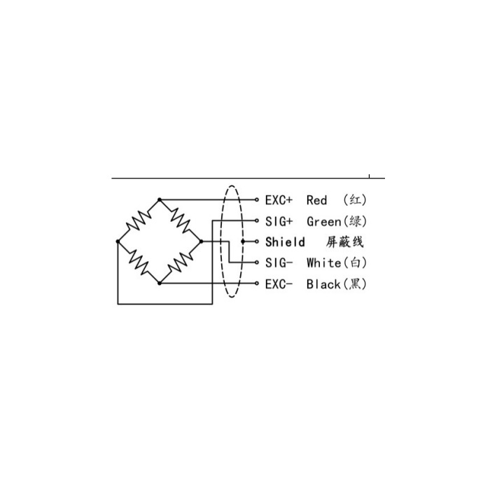
The bridge requires 5-12 V DC excitation and lists 1000 +/-30 ohms input resistance and 1000 +/-5 ohms output resistance. Its cable is 3 m long and 3 mm in diameter. Secure the cable so it cannot pull on the miniature fixture during travel, then check low-force stability with the final reader and motion equipment operating. Working temperature is -20 to +70 deg C and housing protection is IP66. Include fixture heating and cable movement in the test conditions rather than relying only on a stationary bench result.
For a fixture that applies compression through a small top button instead of opposed studs, compare the different mounting arrangement of MV-LC0116.
Stud changes and force reversal
Q1. Can a 50 kg version use couplings made for the 30 kg unit?
The listed stud designation changes from M5 to M6. Review the mating parts, installed length and axial load path before changing capacity. A similar diaphragm housing does not preserve the threaded connection.
Q2. Does zeroing remove the effect of a twisted coupling?
It can hide the initial indicated offset, but not a parasitic force or moment that changes during movement or reversal. Correct the attachment geometry and repeat the relevant loading checks. Compare both directions if the fixture will push and pull.
Q3. Is nominal 1.5 mV/V enough to copy the old span?
The sensitivity tolerance is +/-10%, so the actual rated output matters. Read the delivered sensor data and calibrate the new assembled channel. Reusing a plausible zero and the old gain is not a verified replacement procedure.
